Nebulae - Granular Looper Pedal
A port of the Qu-Bit Nebulae v2 granular looper to a guitar pedal, running on an Electrosmith Daisy Seed3 in a PedalPCB Terrarium platform
Phase vocoder and granular processor running in parallel off a shared 120-second live buffer, with a blend between them
Credits
| Original engine | Stephen Hensley / Qu-Bit Electronix, a_granularlooper.instr (Csound, 2017), QB_Nebulae_V2 |
| Blend rework | alex-thibodeau , a 2-way engine blend with independent dry/wet |
| Hardware platform | PedalPCB Terrarium |
| DSP module | Electrosmith Daisy Seed3 |
This is a transcription from the original Csound source, not a reimplementation from
descriptions. Every sound-producing constant (the tanh/cubic density curve, the 0.20 RMS
ceiling, the seven grain windows, the constant-power blend laws, mincer's FFT size and
phase-locking) was taken from the instrument file and validated numerically against a
Python reference before any firmware was written.
License: MIT. The upstream Qu-Bit firmware is MIT (Copyright © 2019 Qu-Bit Electronix, Inc.), so this port carries that forward alongside its own copyright. See LICENSE. MIT permits use, modification, distribution and commercial use; the only obligation is to keep the copyright notice and permission text with the source. libDaisy is likewise MIT.
Architecture
                       live input
                           |
                    +------+------+
                    |  DC block   |
                    +------+------+
                           |
          +----------------+----------------+
          |           record buffer         |   120 s mono float32, A/B double-buffered
          |        (volatile, SDRAM)        |   46.1 MB of 64 MB
          +----------------+----------------+
                           |
              +------------+------------+
              |        syncphasor       |<---- LFO 1  read position
              |                         |<---- LFO 2  loop length
              +--+-------------------+--+
                 |                   |
        +--------+------+   +--------+---------+
        | mincer        |   | partikkel        |
        | phase vocoder |   | granular         |
        | FFT 2048      |   | max 10 grains    |
        | 4x overlap    |   | spray, pitch rnd |
        | phase-locked  |   | RMS limiter 0.20 |
        +--------+------+   +--------+---------+
                 +---------+---------+
                     BLEND  constant power
                           |
          record tap ------+
                           |
                     freq shifter   page 3
                           |
                       bandpass     page 3  <---- LFO 2 (optional destination)
                           |
                     output gain ---- soft limiter ---- out
The record tap is taken before output gain and before the page-3 effects, so neither monitoring level nor the shifter and filter ever reach the buffer. Effects are monitoring and playback only, applied once, non-destructive.
Hardware
Required
| Item | Notes |
|---|---|
| PedalPCB Terrarium (PCB351) Rev 2 | |
| Daisy Seed3 | 64 MB SDRAM, USB-C. Seed 1 also works |
| 125B enclosure | |
| 6 x B10K 16 mm pots | POT2 and POT5 must be CENTER DETENT (Speed and Pitch) |
| 4 x SPDT ON/ON toggle, 6 mm | standard solder-lug pedal toggle, same footprint as every other PedalPCB board |
| 2 x SPST momentary footswitch | not 3PDT latching |
| 2 x LED + resistors | |
| 2 x 20-pin female header |
Passives per the Terrarium build doc. Note C2/C3/C6 are specified MLCC, not film. At 1 µF the footprint is 2.5 mm lead pitch, which does not exist in film.
Pin map (Terrarium Rev 2)
PedalPCB labels the header pins GPIO n; libDaisy calls the same pin D(n−1).
| Control | PedalPCB | libDaisy | Control | PedalPCB | libDaisy | |
|---|---|---|---|---|---|---|
| POT1 | GPIO17 | D16 / A1 | SW1 | GPIO11 | D10 | |
| POT2 | GPIO18 | D17 / A2 | SW2 | GPIO10 | D9 | |
| POT3 | GPIO19 | D18 / A3 | SW3 | GPIO9 | D8 | |
| POT4 | GPIO20 | D19 / A4 | SW4 | GPIO8 | D7 | |
| POT5 | GPIO21 | D20 / A5 | LED1 | GPIO23 | D22 | |
| POT6 | GPIO22 | D21 / A6 | LED2 | GPIO24 | D23 | |
| Audio in | pin 16 | AUDIO_IN_L | FS1 | GPIO26 | D25 | |
| Audio out | pin 18 | AUDIO_OUT_L | FS2 | GPIO27 | D26 |
Controls
Three pages of knob assignments, selected by SW1 and FS1.
| Page | How to reach it | Labelled on the panel |
|---|---|---|
| 1, primary | SW1 down | yes |
| 2, shift | SW1 up | yes |
| 3, tertiary | SW1 up and FS1 held | no |
Page 3 lasts only as long as you hold FS1. Release and you are back on page 2.
Full matrix
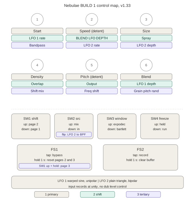
| Pot | 1 Primary | 2 SHIFT | 3 TERTIARY |
|---|---|---|---|
| POT1 | START, loop start | LFO 1 RATE | BANDPASS freq |
| POT2 | SPEED (detent) | BLEND LFO DEPTH | LFO 2 RATE |
| POT3 | SIZE, loop length | SPRAY | LFO 2 DEPTH |
| POT4 | DENSITY | OVERLAP | SHIFT MIX |
| POT5 | PITCH (detent) | OUTPUT | FREQ SHIFT |
| POT6 | BLEND | LFO 1 DEPTH | GRAIN PITCH RAND |
| Switch | 1 Primary / 2 SHIFT | 3 TERTIARY |
|---|---|---|
| SW1 | SHIFT, selects page 1 or 2 | |
| SW2 | SRC, MIX or IN | flip = toggle LFO 2 to bandpass |
| SW3 | WINDOW, expodec or bartlett | (free) |
| SW4 | FREEZE, held or run | (free) |
| FS1 | tap = bypass, hold 1 s = reset pages 2 and 3 | hold = page 3 |
| FS2 | tap = record, hold 1 s = clear buffer |
Page-3 defaults: bandpass centre (off), LFO 2 rate 0.02 Hz, LFO 2 depth 0, shift mix full wet, freq shift centre (off), pitch rand 0.
Page 1, primary
| START | Loop start position within the recording |
| SPEED | -4x to +4x. Centre detent is unity. Negative is reverse |
| SIZE | Loop length, squared curve, scaling the space between Start and the end |
| DENSITY | Grain trigger rate, 0.12 to 983 Hz, hybrid tanh and cubic curve |
| PITCH | -3 to +2 octaves. Centre detent is unity |
| BLEND | Constant power across vocoder, dry and granular |
POT2 and POT5 are centre detent, and the detent lands exactly on unity for both. The module uses encoders here; the knob curve is remapped so a pot behaves the same way.
Page 2, shift
| LFO 1 RATE | 0.02 to 2 Hz, exponential. Default 0.02 Hz, one cycle every 50 seconds |
| BLEND LFO DEPTH | LFO 1 to Blend, unipolar, squared curve. Default 0 |
| SPRAY | Grain position randomisation, squared curve |
| OVERLAP | Grain length as a multiple of the grain period |
| OUTPUT | Monitoring level only, never reaches the recorder |
| LFO 1 DEPTH | 0 to a full loop, squared curve. Default 0 |
SPRAY is the module's Start secondary, restored. At zero every grain spawns from the playhead, so concurrent grains all read identical audio and differ only in envelope phase. The result is successive stutters rather than a cloud. Turning it up spawns grains from random positions across the loop. This is the control that makes it sound granular.
BLEND LFO DEPTH routes LFO 1 to Blend as a second destination. It shares LFO 1's rate on SHIFT+POT1 but keeps its own depth, independent of the read-position depth on POT6.
Unipolar, matching the read-position path: the Blend knob is the floor of the sweep and the LFO only pushes upward from it, so you always know where the bottom is.
depth 0.50 -> Blend at 0.50 sweeps 0.50 to 0.75
depth 1.00 -> Blend at 0.50 sweeps 0.50 to 1.00
One consequence: it only sweeps toward granular. With Blend at centre the motion runs dry to granular, never toward the vocoder. To sweep into vocoder territory, set Blend low and let the LFO rise through dry.
Input is recorded at unity. There is no input level control.
OUTPUT never reaches the recorder, so boosting it does not make overdubs compound on themselves.
Page 3, tertiary
Hold FS1 while SW1 is up. There are no panel labels for these.
| BANDPASS | Centre is off. CCW sweeps down to 120 Hz, CW up to 6 kHz |
| LFO 2 RATE | 0.02 to 2 Hz, exponential |
| LFO 2 DEPTH | 0 to plus or minus one octave of loop length, squared curve |
| SHIFT MIX | Blends shifted against dry. Default full wet |
| FREQ SHIFT | Centre is off, then 0.5 Hz to 100 Hz either side |
| GRAIN PITCH RAND | Per-grain detune, 0 to plus or minus 120 cents |
The page-3 toggle latch
Hold page 3 and flip SW2 either direction. LED2 blinks to confirm, and LFO 2 now modulates the bandpass as well as loop length. Flip again to turn it off.
The firmware reads the flip, not the position. Entering page 3 takes a reference and never acts on it, so the page cannot adopt wherever the lever happens to be sitting. Which way you flip is irrelevant; only the transition counts.
SW2 keeps doing its normal SRC job throughout, including during page 3, so the lever never lies about its own state. That means a page-3 flip also changes SRC, which is the deliberate trade: an extra flip is better than a switch whose position means nothing.
SW3 and SW4 have no page-3 assignment, so the same latch pattern could be extended to them at one flip each and no knobs. Standing preference is not to: both already carry a primary function, and stacking more onto a lever is the kind of overloading this design keeps trying to remove. See the Build 2 section, Tier 2 A4.
Catch and pickup
No secondary ever jumps to wherever the shared knob happens to sit. Nothing adopts on a page change, on the first visit, or at power-on.
On page 1 this is pure catch: the parameter waits indefinitely until the knob crosses its stored value. The panel legend means something there, so knob position stays honest.
On pages 2 and 3 catch has a give-up threshold. If you turn a knob more than about 15% of its travel without crossing the stored value, it stops waiting and takes over where you are, crossfading over 25 ms so there is no click. That fixes the case where a stored value sits at an extreme: without it, a parameter defaulting to 0.0 needs a full counter-clockwise sweep before it responds at all, and reads as dead.
Merely changing pages never causes a takeover. The travel counter resets on every page change, so a jump only ever follows a deliberate turn.
Footswitches and LEDs
| FS1 | tap (on release) = bypass, hold 1 s = reset pages 2 and 3 |
| FS2 | tap = record, hold 1 s = clear buffer |
| LED1 | lit = engaged |
| LED2 | lit = recording, blinks = buffer cleared, blinks = page-3 latch changed |
FS1 in detail
FS1 does three different jobs depending on SW1 and how long you hold it.
| SW1 | Action | Result |
|---|---|---|
| down | tap | bypass toggles, on release |
| down | hold 1 s | resets every page 2 and page 3 parameter to its default |
| up | hold | page 3, for as long as it is held |
| up | tap | nothing |
With SW1 up, FS1 will not bypass. While SW1 is up, FS1 is the page-3 modifier, so it neither toggles bypass nor starts the reset timer. Whatever bypass state you were in is held, so if the pedal was engaged, LED1 stays lit and you cannot switch it off. Flip SW1 down first, then tap FS1. The reset is likewise only reachable with SW1 down.
Bypass fires on release, not press, so that holding FS1 for a reset does not also flip bypass on the way in. That costs a few hundred milliseconds, imperceptible by hand.
The reset
Holding FS1 for one second with SW1 down returns all nine page-2 and page-3 parameters to their power-on defaults: LFO 1 rate and depth, dub level, spray, overlap, output, LFO 2 rate and depth, bandpass, shift mix, freq shift and pitch rand.
Page 1 is not touched, so Pitch and Speed are not reset. Their centre detents are the reset for those two: the detent lands on exactly 1.0000 in both cases.
Page 1 is deliberately untouched. Resetting it would leave all six knobs uncaught and the pedal would ignore every control until each was swept. After a reset the affected pots are uncaught, which is the point: the hidden pages go back to a known state.
It is kept separate from the FS2 buffer clear.
Effects (page 3)
Three processors, applied after the record tap. They are monitoring and playback only: the buffer never contains them, so overdubbing with an effect engaged neither bakes it in nor compounds it across passes. Chain order is freq shifter, then bandpass.
Freq shift
Bode-style single-sideband shifter: Hilbert transform through two 4-section allpass chains (Niemitalo coefficients), then quadrature modulation against a quadrature oscillator, one sideband only. That detail is what makes it inharmonic rather than ring mod. Image rejection measured at 46 dB.
Dead zone at centre, then exponential 0.5 Hz to 100 Hz each side, so most of the travel sits in the 1 to 30 Hz zone where sidebands colour the tone without destroying pitch.
1:00  ->   1.3 Hz     slow beating
2:00  ->   3.8 Hz
3:00  ->  11.2 Hz     sidebands start reading as timbre
4:00  ->  33.5 Hz
5:00  -> 100.0 Hz
An earlier version ran 2 Hz to 2 kHz. Everything past about 3:30 read as a resonant sweep rather than a shift, so two thirds of the knob were unusable.
SHIFT MIX (POT4) blends shifted against dry. Hearing both together is the classic Bode usage: the two beat against each other, which reads as movement rather than the flat detune of a fully wet shift. Around halfway is where the beating is strongest.
Bandpass
TPT state-variable filter, 12 dB/oct, Q of 1.0, last in the chain. Centre is off. The wet amount fades in over the first 15% of travel either side, so there is no jump leaving the dead zone, and the frequency mapping is exponential so the knob tracks pitch.
0.00 ->  120 Hz
0.25 ->  339 Hz
0.50 ->  OFF
0.75 -> 2257 Hz
1.00 -> 6000 Hz
A bandpass throws away everything outside its passband, so perceived level drops even though the peak itself is unity: measured -14 dB at 200 Hz against -0.7 dB at 6 kHz before compensation. Makeup gain scales with wet amount, reaching about +5 dB fully engaged.
24 dB/oct was considered and rejected. A steeper filter removes more energy, so it gets quieter, not louder. Makeup gain is the right lever.
With the page-3 latch on, LFO 2 sweeps it bipolar and exponential, plus or minus 2 octaves at full depth, centred on whatever the knob is set to. Clamped to 40 Hz and 12 kHz, so extreme settings narrow the sweep rather than wrapping.
knob sets     lfo -1     lfo +1     span
   339 Hz        85       1356      4.0 octaves
  2257 Hz       564       9026      4.0 octaves
  6000 Hz      1500      12000      3.0 octaves
Grain envelope, expodec
The decay is two exponentials summed, a fast component plus a slow one. A single exponential cannot be both snappy and long-tailed, because how fast it falls and how far it falls are the same number, so lengthening the tail always softens the initial drop. Two stages behave like a plucked string instead: the transient bites, then a low tail hangs on.
                to -6dB   to -12dB   to -20dB    mean
single exp        15.8      25.2       37.7     0.1460
two-stage         11.9      22.3       50.6     0.1463
Percentages of grain length; the attack is a fixed 6.25% in both. Snappier at the top, longer at the bottom, and the mean is unchanged so it needs no level compensation. Both endpoints are exactly zero and the decay never rises, so grain boundaries stay silent.
Everything scales with grain length, so the change reads as proportional opening rather than a fixed release time and is most obvious at long grains.
Grain pitch randomisation
The module's Pitch secondary, restored. Each grain gets its own detune, assigned once at launch and held for that grain's life. Per grain, not per sample: per sample would be FM.
Stock is rand(amt * 1200), bipolar cents, so plus or minus an octave at full. That is far
too wide to stay musical, so this uses a squared curve to plus or minus 120 cents.
knob   max cents   rms cents
0.25      7.5         4.3
0.50     30.0        17.3
0.75     67.5        39.0
1.00    120.0        69.1
Quarter travel is chorus territory. Half is audible detune. Most of the knob stays subtle. RMS runs about 58% of the maximum because the distribution is uniform, so typical grains sit well inside the extreme.
Pair it with SPRAY. Spray decorrelates where grains read, pitch rand decorrelates how fast. Together they are what makes the grain cloud sound like a cloud.
LFO 1, read position
An addition, not part of the original module. It modulates read position only.
Shape
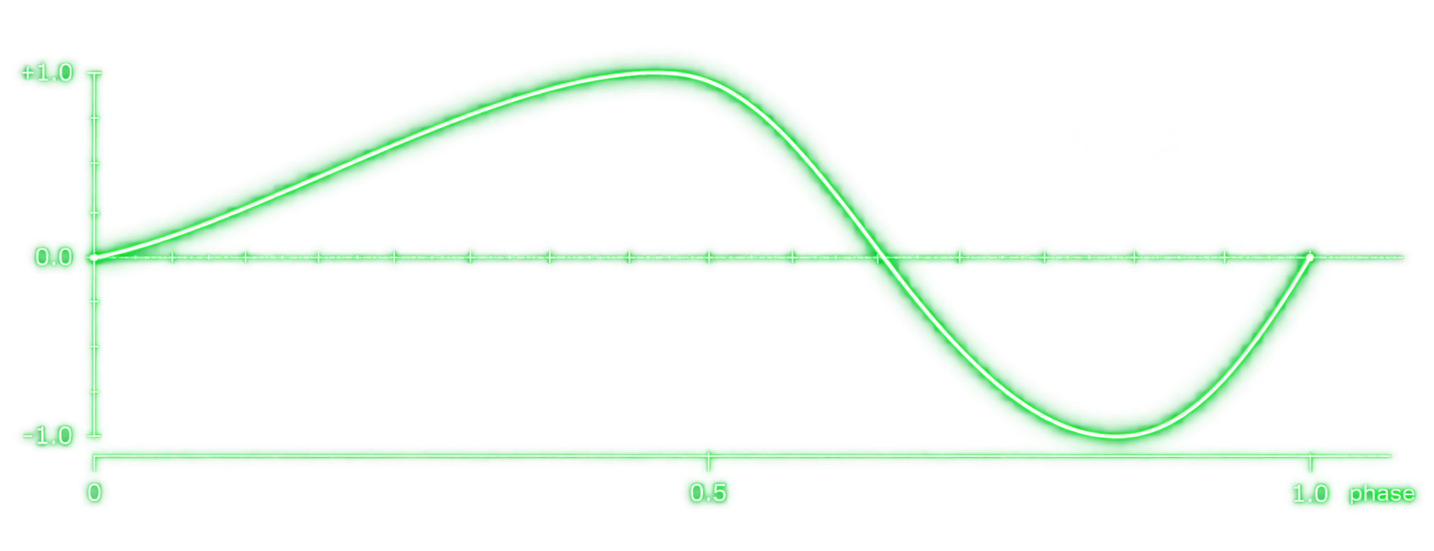
A sine with its phase warped before the sine is taken:
warp(p) = p / (2s)                    for p < s
          0.5 + (p - s) / (2(1 - s))  for p >= s
out     = sin(2 * pi * warp(p))
s is the skew, fixed at 0.65. At s = 0.5 this reduces to an ordinary sine.
The warp stretches the first 65% of the cycle across the first half of the sine and compresses the remaining 35% into the second half, so the rise is slow and the fall is quick. It stays smooth throughout, with no corners or discontinuities.
One cycle sampled in 24 steps, against a pure sine:
skew 0.65  +0.20 +0.39 +0.57 +0.72 +0.85 +0.94 +0.99 +1.00 +0.97 +0.90 +0.80 +0.66
           +0.50 +0.32 +0.12 -0.15 -0.50 -0.78 -0.96 -1.00 -0.90 -0.68 -0.37  0.00

sine       +0.26 +0.50 +0.71 +0.87 +0.97 +1.00 +0.97 +0.87 +0.71 +0.50 +0.26 -0.00
           -0.26 -0.50 -0.71 -0.87 -0.97 -1.00 -0.97 -0.87 -0.71 -0.50 -0.26  0.00
The rise takes 15 of 24 steps; the fall takes 9.
How it moves the sound
It offsets read position, not loop geometry. Loop start and loop length are computed before the LFO is applied and are never touched by it, so playback rate and loop boundaries stay fixed. Only the point being read within the loop moves.
It is unipolar. The sine's -1 to +1 range is mapped to 0 to +1, so the offset only ever pushes forward from the playhead, never behind it. The sweep therefore anchors at the Start position.
uni  = (sin_out + 1) * 0.5          ->  0 to 1
read = phasor + uni * depth^2
Depth is squared. At full depth the offset covers an entire loop, so the read position scans forward through the whole buffer and returns.
Both engines follow it together, since they share the read position. The vocoder time-warps as the read point moves and grains spawn from the moving position. At low depth this is tape-like wobble; at high depth it becomes a slow scan through the loop.
Rate is 0.02 to 2 Hz, exponential (50 seconds per cycle at the slow end).
The asymmetry is what reads as motion rather than oscillation. A symmetric sine feels like rocking in place; this drifts forward and resets.
Controls
| SHIFT + POT1 | LFO 1 RATE |
| SHIFT + POT6 | LFO 1 DEPTH (0 = off, output is bit-identical to no LFO) |
Blend is a second destination, on SHIFT+POT2. It shares this rate knob but has its own depth, so read position and Blend move together in time at whatever amounts you set. Both are unipolar, anchored at their knob positions. In build 2 both LFOs reach every destination through bipolar attenuverters instead.
LFO 2, plain triangle
Page 3. Rate on POT2, depth on POT3. Normalled to loop length, and routable to the bandpass as a second destination by flipping SW2 while page 3 is held.
Deliberately the dull one. Where LFO 1 is a phase-warped sine with character, this is the symmetric triangle a sampler gives you: bipolar, no skew parameter, no output curve. When you want obvious motion rather than shape, this is the one to reach for.
-0.75 -0.50 -0.25 +0.00 +0.25 +0.50 +0.75 +1.00 +0.75 +0.50 +0.25 +0.00 -0.25 -0.50 -0.75 -1.00
Computed per sample rather than per block, so its corners land exactly. At block rate a corner can be up to one block late, which at 2 Hz is 2% of the period and harmless, but the per-sample form costs almost nothing and removes the question.
Loop length, the normalled destination
Bipolar, multiplying loop length by 2^(depth^2 * lfo), so full depth breathes between half
and double length while the playhead rate follows inversely. Multiplicative, so it feels
uniform across Size's squared curve. Recording uses the unmodulated length, so the
buffer itself never breathes, only playback.
Earlier versions gave LFO 2 a skew that tracked its own rate. That came out in v1.33: with LFO 1 already providing a shaped waveform, a second shaped one was redundant, and a plain triangle is more useful as a contrast.
How to use it
Load your first loop
- SW2 to IN
- Tap FS2, recording starts
- Play
- Tap FS2, recording stops
In IN mode nothing else affects what is recorded. Loop length is set by where you stop.
Hear it
- BLEND sets the mix. Fully CCW is the phase vocoder, centre is dry, fully CW is granular
- SPRAY (SHIFT+POT3) is what turns stuttering into a grain cloud
- DENSITY and OVERLAP shape the texture. Under FREEZE, grain length is the stutter length, so Overlap makes it longer and Density retriggers it faster
Overdub
- SW2 to MIX
- Tap FS2 once
Recording punches in at the current playhead, runs exactly one loop pass, and stops itself. You do not tap FS2 again. Loop length is locked, so an overdub cannot shorten the loop.
The record source is engine output plus your input, independent of BLEND, and recorded at unity. Page-3 effects are not captured, so overdubbing with the shifter up will not bake it in or compound it across passes.
Reach page 3
With SW1 up, hold FS1. Release to return to page 2. Every page-3 control needs catching, but the give-up threshold means about a sixth of a turn is enough.
Clear and reset
Hold FS2 one second to clear the buffer. Hold FS1 one second, with SW1 down, to reset pages 2 and 3 to defaults. LED2 blinks either way.
Considerations
- The buffer is volatile. Power down loses it
- Layers are mixed destructively into one buffer. There is no undo and no way to adjust a layer after it is recorded
- With SIZE below maximum an overdub covers only that fraction of the loop and stops early. That is stock behaviour, since the module ties overdub length to loop size the same way
- At unity speed and unity pitch with SPRAY and PITCH RAND at zero, every concurrent grain reads identical audio and differs only in envelope phase. That is why it sounds stuttery rather than granular. Raise either one, or move PITCH off its detent
- A page-3 flip of SW2 also changes SRC, by design. The lever never lies about its own physical toggle position

Versions
Current: nebulae_v1.33-BUILD1.bin
The two builds are now separate lines. Build 1 is the 1.x firmware on this page.
Build 2 is 2.x, built with make EXTRA_DEFS=-DBUILD2=1, and is documented under Build 2
plans. A release ships only the binary for the build it is for: no BUILD2 binary appears in
a 1.x release and no BUILD1 binary in a 2.x one.
| Version | Change |
|---|---|
| 1.33 | Current. LFO 2 becomes a plain symmetric triangle, bipolar, no skew, computed per sample. SHIFT+POT2 becomes BLEND LFO DEPTH: LFO 1 to Blend, unipolar, sharing LFO 1's rate but with its own depth. DUB LVL removed, input records at unity |
| 1.32 | Built on v1.27. Two-stage grain decay: a fast component plus a slow one, so the transient bites harder than before while the tail hangs on longer. Record tap moved ahead of the page-3 effects, so they are non-destructive. DUB LVL kept on SHIFT+POT2 |
| 1.31 | Superseded. Same decay change but built on v1.27 while labelled as v1.29, so it lacked the record-tap move. Replaced by 1.32, which is the same idea on a verified base |
| 1.30 | Superseded. LFO 2 rate narrowed to 0.05 to 1.5 Hz, but built on a tree mistaken for v1.29. The range is still wanted; see Build 2 plans O3 |
| 1.29 | Record tap moved ahead of the page-3 effects. SHIFT+POT2 became BLEND LFO DEPTH and DUB LVL was removed, both reverted in 1.32 |
| 1.28 | Expodec decay floor 0.001 to 0.003, lengthening the tail by shallowing the bend. Superseded by 1.32's two-stage decay, which lengthens the tail without softening the attack |
| 1.27 | LED2 blinks to confirm the FS1 parameter reset on both builds |
| 1.26 | Page-3 LFO latch moved to SW2, which keeps its normal SRC job throughout |
| 1.25 | LFO 2 routable to the bandpass by flipping a toggle while page 3 is held, LED2 confirms |
| 1.24 | Grain pitch randomisation on page 3. LFO 2 skew now follows its own rate. Phaser removed |
| 1.23 | Catch gains a 15% give-up takeover on pages 2 and 3. Page 1 stays pure catch |
| 1.22 | Phaser deepened to 3 chains and 10 stages. Bandpass makeup gain |
| 1.21 | Page 3 rearranged. Phaser speed tracked the LFO 2 rate |
| 1.20 | Sweepable bandpass, last in the chain |
| 1.18 to 1.19 | Barber-pole phaser, later removed |
| 1.17 | Size LFO skew exposed, later folded into rate |
| 1.16 | Size LFO shape: mirrored skew plus an output curve |
| 1.15 | Freq shift dry/wet mix |
| 1.14 | Freq shift range cut to 0.5 Hz to 100 Hz. The old 2 kHz top read as a resonant sweep |
| 1.13 | Reset moved to FS1 hold. Bypass moved to release |
| 1.12 | Parameter reset for pages 2 and 3 |
| 1.11 | Build 2 variant gated behind a single BUILD2 define |
| 1.10 | Third page on SW1 up plus FS1 held. Size LFO and freq shifter. Catch generalised to three pages |
| 1.9.7 | OUTPUT no longer reaches the recorder. With output boosted, every overdub had been writing the loop back louder and compounding |
| 1.9.6 | DUB LVL boots at unity. The init still meant unity on the old input-level curve but -12 dB on the new one |
| 1.9.5 | Record source is engine output plus input, independent of BLEND. At either Blend extreme the dry factor is zero, so overdubs had captured engine output only |
| 1.9.4 | SPRAY on SHIFT+POT3, ported from the Csound. Window moved onto the SW3 toggle |
| 1.9.3 | Record fixed. The overdub latch check ran before the engine had acted on a fresh tap, so it cleared the latch on the block that set it |
| 1.9.1 | Punch-in overdub. Also fixed a v1.9 bug where booting with SHIFT up made the shift page adopt knob positions outright |
| 1.9 | Catch resumes without a re-catch only if the parameter was live when leaving the page |
| 1.8 | RMS limiter moved to control rate. Fixed the grain crackle at high Overlap |
| 1.7 | Skip the engine whose blend coefficient is exactly zero |
| 1.6 | Output level on SHIFT+POT5 |
| 1.5 | Unipolar LFO depth. Catch tolerance widened from 0.2% to 2% |
| 1.1 to 1.4 | Catch adopt, expodec floor, LFO curve, density taper. All reverted |
| 1.0 | Audio block size 64 to 512. The critical fix, see below |
| 0.1 to 0.9 | Bring-up: clear, LFO, heartbeat, input level, pot smoothing, FTZ, DC block, soft limit |
Two branches. The 1.x line is the maintained one. 2.x-ALEXTBLEND keeps the 2-way
engine blend with dry on its own knob, but has no SPRAY, no page 3 and no effects.
Controls for the 2.x-ALEXTBLEND branch (click to expand)
The 2.x branch replaces the stock 3-way blend with a 2-way engine crossfade and moves dry onto its own control. Under the stock law the vocoder and grains never overlap, since voc fades out by centre and grain fades in after it. The 2.x law lets both sound together.
| Primary | SHIFT | |
|---|---|---|
| POT1 | START | LFO RATE |
| POT2 | SPEED (detent) | DRY/WET |
| POT3 | SIZE | WINDOW |
| POT4 | DENSITY | OVERLAP |
| POT5 | PITCH (detent) | OUTPUT |
| POT6 | BLEND, vocoder to granular only | LFO DEPTH |
BLEND becomes purely the balance between the two engines. Centre gives 0.707 of each rather than pure dry. DRY/WET on SHIFT+POT2 is the main output mix and boots fully wet.
This branch has no SPRAY, no page 3 and no effects section, and its Window is still on a knob. It is far behind the 1.x line and is kept only for anyone who prefers that blend behaviour.
Deviations from stock
| Mono | Terrarium is single in / single out. Loses grain stereo spread |
| 120 s buffer | vs 5 min. Volatile, with no file, USB, SD or sample loading anywhere |
| Secondaries mostly dropped | Most _alt params fixed at 0, which is stock-at-defaults. SPRAY and grain pitch rand are restored |
| Speed/Pitch remap | Centre detent lands on unity. Endpoints preserved exactly. The module uses encoders, we use pots |
| SPRAY, OUTPUT | SPRAY is the module's Start secondary, restored. OUTPUT is an addition, since the Terrarium is unity gain throughout |
| Effects are non-destructive | The record tap sits ahead of them, so the buffer never contains freq shift or bandpass and overdubs cannot compound the effect |
| Overdub ignores BLEND | Stock scales the recorded dry by the blend dry factor, which is zero at both extremes. Correct for the module, wrong for a looper |
| Catch mode | One pot serving two parameters requires it |
| Expodec window | Replaces the stock linear ramp-down, on a toggle so it can be A/B'd |
| LFO 1 | Not stock. Modulates read position only, so loop geometry is untouched |
| LFO 2, freq shift, phaser, bandpass | Not stock. Page 3 additions. Freq shift uses the Hilbert core from kuttor's SuperNova firmware with a re-mapped range. The barber-pole phaser is an original implementation of a well-documented algorithm class |
| Input/output level | Terrarium is unity gain; a guitar sits ~20 dB below where the grain RMS limiter engages |
| DC block, output soft limit, block size 512 | Platform necessities |
Freeze and Reset are not on footswitches: Freeze is literally kspeed = 0 in the original,
so a toggle does it, and Reset only mattered for CV sync.
Notes from the port
Block size was the one serious bug. mincer computes an entire frame (two forward
FFTs, one inverse, two 1025-bin loops, and a 2048-sample interpolated SDRAM read) inside a
single audio callback. At 64 samples that's 1.33 ms of budget against ~1.4 ms of work, so
one block in eight overran: a dropout 94x/second that sounded like digital garble. Nebulae
itself runs Csound on a Pi with a ~42 ms output buffer, so its frame work is invisible.
Sample-exact diffing is the wrong test for a phase vocoder. div = 1/(hypot(prev)+1e-20)
reaches ~1e20 at empty bins, so float rounding compounds through the feedback path. Frame 0
matches the reference to 7.4e-08; after that the waveforms diverge while remaining
spectrally identical to −58 dB. Acceptance criteria are frame-0 agreement, unity gain, exact
pitch ratios and magnitude spectrum. The granular side, being non-recursive, is held to
sample-exact and passes at 2e-07.
giHamming is not Hamming. The instrument declares ftgen 20, 9, 1 and comments it
"Hamming Window". GEN20 type 9 is Sinc. This matters: sinc reaches exactly 0 at both
endpoints, a real Hamming bottoms at 0.08 and would click at every grain boundary.
The grain RMS stage is a limiter, not a leveler. Identity below 0.20, attenuation above. It never boosts, which is why input level matters on a guitar-level platform.
Density never reaches its stated 2500 Hz. The hybrid tanh/cubic scalar tops out at 0.906, so the real maximum is ~983 Hz.
Building from source
git clone --recursive https://github.com/electro-smith/libDaisy.git
cd libDaisy && make -j
cd .. && mkdir nebulae && cd nebulae
# copy in: main.cpp terrarium.h nebulae_dsp.{h,cpp} nebulae_engine.{h,cpp} Makefile
make                          # -> build/nebulae.bin  (build 1)
make EXTRA_DEFS=-DBUILD2=1    # -> build 2, button and bi-colour LED
TARGET = nebulae
CPP_SOURCES = main.cpp nebulae_dsp.cpp nebulae_engine.cpp
LIBDAISY_DIR = ../libDaisy
SYSTEM_FILES_DIR = $(LIBDAISY_DIR)/core
include $(SYSTEM_FILES_DIR)/Makefile
On Windows, Electrosmith's Daisy Toolchain installer bundles arm-none-eabi-gcc, make and
dfu-util.
License
MIT. See LICENSE.
- Original engine © 2019 Qu-Bit Electronix, Inc. (MIT)
- Blend rework derived from alex-thibodeau's fork (inherits MIT)
- This port © 2026 Kenny Rakentine (MIT)
- libDaisy © Electrosmith (MIT)
If you fork this, keep all four attributions.
Build 2 plans
Waiting on a Terrarium PCB restock. Everything else is ordered or on hand.
How to read this section
Build 2 has been designed more than once. Rather than deleting older plans, they are kept as tiers. Nothing below is dead unless it is in Tier 4.
| Tier | Meaning |
|---|---|
| 1, PRIMARY | The current plan. Build this unless there is a reason not to |
| 2, ALTERNATE | Superseded but coherent and buildable. Each entry says what replaced it and why |
| 3, OPEN | Undecided or unverified. Resolve before assembly |
| 4, REJECTED | Ruled out, with the reason, so it is not re-proposed |
When a Tier 1 entry changes, the old version moves to Tier 2 rather than being removed.
TIER 1, PRIMARY
Design settled. This is the layout to build.
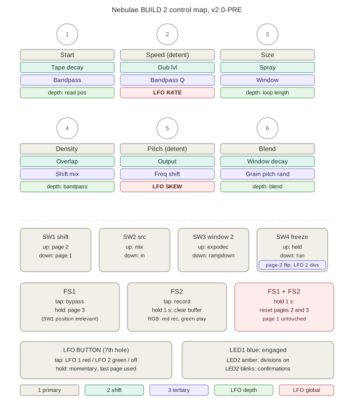
Panel
SW1 stays a toggle. A seventh hole is added for an illuminated momentary button with a bi-colour LED, which carries the LFO layer. LED2 at FS2 becomes a red/green bi-colour.
Knobs
| Pot | 1 Primary | 2 Shift | 3 Tertiary | LFO page, both |
|---|---|---|---|---|
| 1 | START | TAPE DECAY | BANDPASS freq | depth to read position |
| 2 ● | SPEED | DUB LVL | BANDPASS Q | LFO RATE |
| 3 | SIZE | SPRAY | WINDOW | depth to loop length |
| 4 | DENSITY | OVERLAP | SHIFT MIX | depth to bandpass |
| 5 ● | PITCH | OUTPUT | FREQ SHIFT | LFO SKEW |
| 6 | BLEND | WINDOW DECAY | GRAIN PITCH RAND | depth to blend |
Every page-2 and page-3 control keeps the pot it has today. Only the four slots freed by the LFO rework are newly filled: tape decay, bandpass Q, window, window decay.
Switches, footswitches, LEDs
| SW1 | SHIFT, page 1 or 2 |
| SW2 | SRC mix or in |
| SW3 | WINDOW slot 2: expodec or rampdown |
| SW4 | FREEZE. Page-3 flip toggles LFO 2 divisions, LED2 confirms |
| FS1 | tap = bypass. Hold = page 3, regardless of SW1 |
| FS2 | tap = record, hold 1 s = clear buffer |
| FS1 + FS2 | hold 1 s = reset pages 2 and 3 |
| Button | tap cycles LFO 1 (red), LFO 2 (green), off. Hold = momentary, last page used |
| LED1 | blue or violet, engaged |
| LED2 | red recording, green playback, amber SOS active, blinks for confirmations |
The reset moves to both footswitches
FS1 + FS2 held together resets pages 2 and 3. That frees FS1's hold to mean page 3 unconditionally, with SW1's position irrelevant.
This is what lets page 3 stay on FS1 without the build 1 collision, where holding FS1 means page 3 with SW1 up and a parameter reset with SW1 down and nothing on the panel says which, so reaching for page 3 with SW1 down wipes both hidden pages instead. Two footswitches at once is unambiguous and impossible to hit by accident.
Worth backporting to build 1 at the next firmware update there.
The LFO layer
Two pages, one per LFO, identical layouts. Which LFO you are editing is the LED colour, not the arrangement. One page per LFO is what makes two fit: each needs a rate and a skew, four controls against two spare knobs.
Pots 2 and 5 carry rate and skew because Speed and Pitch take no LFO, so those knobs are otherwise idle in this layer. Pot 2 already reads Speed, close enough to its LFO-page job to cost nothing. Pot 5 is centre detent, which suits skew: detent at symmetric, CCW one way, CW the other.
Depths are bipolar attenuverters, centre off. Inverting a skewed LFO turns slow-rise-fast-fall into its mirror, which is different motion rather than a phase flip, and on read position it sweeps backward from Start instead of forward. Centre-off also means depth defaults to the middle of its travel rather than an extreme, which sidesteps the dead-knob trap in O2 entirely.
Four destination slots per LFO, mirroring page 1 minus Speed and Pitch, except that bandpass takes Density's slot. Density does not need an LFO; bandpass sweep is already proven on build 1 and would otherwise be a regression. See O5.
Both LFOs reach every destination, including the same one at once. No hard split.
What the four freed slots hold
WINDOW, page 3 POT3. The stock continuous sweep across all seven grain windows,
restored. WinMix already crossfades the whole bank; SW3 merely picks one of two for slot
2. This is the largest sound-shaping control not currently exposed, and it returns to the
pot it occupied before v1.9.4 moved it to a toggle. SW3 keeps slot 2's expodec versus
rampdown choice.
WINDOW DECAY, page 2 POT6. Sweeps the expodec grain envelope from the original single exponential toward a two-stage plucked-string curve.
knob       -6dB      -12dB     -20dB     mean
0.00       15.8      25.2      37.7     0.1460    exactly the v1.27 curve
0.50       14.1      22.7      38.1     0.1414
1.00       11.9      22.3      51.8     0.1510
Knob at zero is bit-identical to the original, not an approximation: the fast component
becomes the whole curve with its time constant set to 1/ln(1000), which is exactly
0.001^t. Turning up introduces the slow component, so the transient sharpens while the
tail stretches. Mean level is flat across the sweep, so it needs no compensation, and both
endpoints stay exactly zero.
It lengthens and sharpens together, which is inherent: a single exponential cannot get a longer tail without softening, so lengthening requires a second stage and that stage is what steepens the front.
BANDPASS Q, page 3 POT2. Fully CCW is exactly 1.0, the shipped value, so the default is the current sound and turning up only adds. Ceiling 4.0.
Q      cycles   at 120 Hz   at 900 Hz   at 6 kHz
1.0      2.2      18 ms       2 ms      0.4 ms    shipped, knob CCW
2.0      4.4      37 ms       5 ms      0.7 ms
4.0      8.8      73 ms      10 ms      1.5 ms    knob CW
6.0     13.2     110 ms      15 ms      2.2 ms    rejected
This topology never self-oscillates: damping is 1/Q and only reaches zero at infinite Q, so
it rings progressively longer instead. Ring time in cycles is constant, so the low end of
the sweep is the worst case and the same Q rings 50x longer at 120 Hz than at 6 kHz. Q=4 at
120 Hz is 73 ms, audibly resonant but not pitched. Q=6 is 110 ms, which is a drone.
TAPE DECAY, page 2 POT1. Undecided. Sound-on-sound: write existing * decay + new so old
layers fade instead of accumulating, which is how a tape loop with a partly-erasing head
behaves. At 0.9 a layer is 20 dB down after 22 passes, at 0.98 it lingers for a hundred.
This is the only genuinely new DSP in build 2; everything else exposes or re-routes code that already exists. The risk is feedback: the engine output sits inside the loop, so both the grain RMS limiter and the output soft limiter end up in the feedback path. That is a tuning job, not a one-line change. The slot is reserved; whether SOS ships is still open.
Firmware status
Preliminary firmware exists: nebulae_v2.0-BUILD2-PRE.bin. BUILD2 now means the
seventh-hole button and bi-colour LED2; the old button-replaces-SW1 arrangement (Tier 2 A1)
has been removed from the source, so SW1 is a toggle in both builds.
Built and verified in software: five catch pages, both LFO pages, all eight depth attenuverters, the window and window-decay knobs, bandpass Q, LFO 2 divisions with loop retrigger, the button state machine and the FS1 + FS2 reset.
Not done: tape decay reads its knob into a variable and does nothing, pending the SOS decision. Untested on hardware: LED colours, button feel, the 350 ms tap threshold.
Pins as built, all flywired from the header underside with 1K per LED leg:
D0  LFO button          D1  button LED red
D2  button LED green    D3  LED2 green   (LED2 red stays on the existing LED2 pin)
LFO 2 on build 2 keeps its skew
Build 1's LFO 2 is a plain triangle with no skew at all. Build 2's keeps a skew knob on pot 5, so it sweeps continuously from reverse saw through triangle to ramp-up saw: skew toward 0 is the reverse saw, quick rise and long fall. Rate runs 0.1 to 15 Hz, which reaches a fast trill, and the per-sample computation is what keeps the corners clean up there.
In division mode the rate instead becomes one of seven whole-number ratios of the loop, from a quarter-cycle per loop to sixteen, and the phase resets when the playhead wraps. Locking the period to the loop is what makes that reset seamless: an unsynced LFO reset mid-cycle steps its output, which clicks on loop length or filter frequency. Fast divisions with a reverse saw are the trill.
Button mounting
The DAIER illuminated tact switch has no nut and no panel bushing, so it cannot be fastened the way a pot or jack is. Mount it on a small perfboard held against the underside of the enclosure top, cap protruding through the hole.
- Position between the two LEDs, slightly lower if it fits. Check clearance against the Terrarium PCB below before committing
- Drill the hole slightly larger than the cap so it does not bind at the end of travel
- Set standoff height so the cap sits proud at rest by more than the switch travel, or it bottoms out on the enclosure before actuating
- Hot glue works but cures rigid and is awkward to remove. Nylon standoffs with double-sided foam, or a shim stack, are easier to revise
- Wire and test the switch before gluing anything
Free Seed pins
D0 to D6, D11 to D14, D24, D27 to D30.
Solder to the underside of the Terrarium female header, never to the Seed itself, so the module stays removable for bench flashing. Do all flywiring before the board goes in the enclosure. Each LED leg needs its own 1K.
Ordered and on hand
Black powder-coated 125B, black toggles, 3 mm red/green bi-colour LEDs, illuminated SPST momentary buttons, Daisy Seed3, centre-detent and plain B10K pots, Lumberg jacks, headers, OPA2134, trimmers, 100 uF polymer rail caps, WIMA film set, Panasonic 10 uF, Davies knobs.
TIER 2, ALTERNATE
A1. Button replaces SW1 in the SW1 hole
Tap latches shift, hold gives page 3. No seventh hole.
This is what the current BUILD2 define actually builds, so it is the only Tier 2 entry
that exists in firmware today.
Superseded by: the seventh hole, because it left FS1 carrying a page-3 hold whose meaning depended on SW1 with nothing on the panel to say which.
Still viable if: drilling a seventh hole proves impractical, or the button cannot be mounted cleanly. Costs no new firmware.
A2. Button is a page-3 modifier only
SW1 stays a toggle, seventh hole added, button is a plain momentary page-3 modifier with its LED lit while held, and FS1's page-3 special case is deleted.
Superseded by: LFO mode, which uses the button for a layer that needs it more.
The problem it solved is now solved elsewhere. On build 1, holding FS1 means page 3 with SW1 up and a parameter reset with SW1 down, and nothing on the panel says which, so reaching for page 3 with SW1 down wipes both hidden pages. Tier 1 moves the reset to FS1 + FS2 instead, which fixes the collision without spending the button on it.
Still viable if: the LFO layer turns out not to be worth a dedicated control, in which case this is the cheapest thing to do with the seventh hole.
A3. Hard split of knobs between the two LFOs
Each knob permanently assigned to one LFO. The button LED indicates which is selected.
Superseded by: two independent LFOs, judged less restrictive and less confusing.
Its one advantage: depth knobs leave the mode entirely, since each knob has exactly one depth value regardless of selection, so you never need to know which page you are on to set a depth. Worth revisiting if two pages of depth values prove hard to track in practice.
A4. LFO destination latches on SW3 and SW4
Additional LFO destinations bought one toggle flip at a time, no knobs required. The pattern already exists on SW2.
Superseded by: continuous per-destination depth in LFO mode, which is strictly more expressive than a fixed-depth on/off latch.
Standing preference against: both toggles already carry a primary function, and stacking more onto a lever is the overloading this design keeps trying to remove.
A5. LFO mode absorbs page 3
The button carried the LFO layer and page 3's contents moved onto pages 1 and 2, so page 3 disappeared entirely and FS1 went back to unconditional bypass and reset.
Superseded by: keeping page 3. The arithmetic never quite worked, since four page-3 survivors had to fit three freed page-2 slots, and the only way to close the gap was to fix SHIFT MIX at a constant. Independent shift mix is one of the more musical controls on the pedal and its adjustability is the point.
What it got right: FS1 returning to one unconditional meaning. Tier 1 now achieves that by moving the reset to FS1 + FS2 instead.
TIER 3, OPEN
O1. RESOLVED. Page 3 is kept
The question was whether page 3 would empty once the LFO destinations moved into the LFO layer, which would have let FS1 return to one unconditional meaning.
Answered by counting. Only four page-3 survivors would have had to fit three freed page-2 slots, and closing that gap meant fixing SHIFT MIX at a constant. Not acceptable: independent shift mix is one of the more musical controls on the pedal.
So page 3 stays, only the LFO rate and depth controls leave it, and the FS1 collision is solved separately by moving the reset to FS1 + FS2. See Tier 1.
O2. RESOLVED. Centre-off depths sidestep the catch trap
The worry was that every LFO depth defaults to zero, an extreme, which is the known shape of the dead-knob trap: a parameter sitting at 0.0 needs a full counter-clockwise sweep before pure catch picks it up. With two LFO pages that would have been every depth knob, twice.
Bipolar attenuverter depths solve it by construction. Off is the centre of travel, not an end of it, so a knob left anywhere lands within reach. The 15% give-up takeover still applies and should extend to both LFO pages, but it is no longer load-bearing.
O3. LFO rate range rework
Confirmed on build 1: LFO 2 past 12:00 CCW is not dead, just extremely slow. The cause is the rate range, not catch and not the detent.
Proposed: raise the slow floor from 0.02 Hz to 0.1 Hz, a 10 second cycle. Keep the 2 Hz ceiling. That narrows the span from 6.6 octaves to 4.3, so every degree of rotation covers less frequency ratio and the whole sweep gains resolution, including the fast end that currently feels narrow.
0.02 to 2 Hz     50.0 s to 0.50 s   6.6 octaves   today
0.05 to 1.5 Hz   20.0 s to 0.67 s   4.9 octaves   built as v1.30, wrong base, not shipped
0.06 to 1.2 Hz   16.7 s to 0.83 s   4.3 octaves   finer still
0.10 to 2 Hz     10.0 s to 0.50 s   4.3 octaves   loses the slow end
0.05 to 1.5 Hz is the one to rebuild. It keeps a genuinely slow floor while cutting the share of travel slower than a 10 s cycle from 35% to 15%, and every tenth of the knob then covers 0.49 octaves instead of 0.66, so the whole sweep is 26% finer. Narrowing both ends keeps the law a single exponential, so equal rotation still covers equal frequency ratio.
Raising the ceiling does the opposite. It widens the span and makes every degree coarser. Only the floor move gets what was asked for.
The 46.9 Hz aliasing limit is in Tier 4 as the hard ceiling. It is nowhere near anything worth setting here.
Measure before changing. Read the actual mapping in the source rather than assuming.
O4. Faceplate artwork
The repo image is Nebulae1.9.7Decal_9-8-26.png. The filename is a version behind.
Previously the artwork was still correct because page 3 was unlabelled. An LFO layer changes that. If pots 2 and 5 carry rate and skew in LFO mode, the panel arguably needs secondary labelling the current decal does not have. Decide before etching.
O5. RESOLVED. Bandpass takes pot 4, Density does not get an LFO
The LFO layer has exactly four depth slots per LFO: pots 1, 3, 4 and 6, since pots 2 and 5 carry rate and skew. Mirroring page 1 would have made those Start, Size, Density and Blend, leaving bandpass with no slot. Build 1 can already route LFO 2 to the bandpass at plus or minus 2 octaves, so build 2 would have shipped with less modulation than build 1: a proven bandpass sweep traded for Density modulation that has never existed on this pedal.
Pot 4 carries bandpass depth. Density does not need an LFO. Size keeps its slot, since it is LFO 2's normalled destination today and loop length breathing is one of the better modulations on the pedal.
The only cost is that pot 4's LFO-page label reads bandpass while its primary label reads Density, the one place the LFO layer stops mirroring the printed panel. Page 3 is kept (see O1), so bandpass frequency stays on page 3 POT1 and no parameter is ever separated from its own depth knob.
O6. Input boost
Undecided. Non-inverting OPA2134 stage between the input jack and the Terrarium IN pad, gain 4 to 6x, 100K trimmer, powered from the board +5 V and VREF, shielded cable routed away from the Seed.
This is the only gain in the chain that can improve signal to noise, since OUTPUT is applied after the converter and lifts signal and noise identically. A guitar currently hits the ADC around 25 dB below full scale, wasting that much converter range.
It does not worsen mixer noise. The mixer is downstream and sees a hotter, cleaner signal, so it needs less makeup gain of its own.
Test it for free first by putting a clean boost pedal in front of the current build and listening on headphones. That is electrically the same experiment.
Gain above roughly 6x clips IC1.1 before the converter sees it, since the audio rail is +5 V with VREF at 2.5 V, giving about 3.5 Vpp of swing.
O7. Terrarium PCB restock
Alert is set. No alternate source exists. PedalPCB has not published Terrarium board files, so there is nothing to send to a fab.
O8. Panel-mount USB-C pigtail
Optional, so the Seed can be reflashed without pulling it. Round hole, avoids cutting a rectangular slot in cast aluminium.
TIER 4, REJECTED
DIP switches
Funbox uses them to select which of several firmwares to load. This project has one engine, and the page latch already covers configuration from the panel without taking the back off.
Audio rate LFO
Block size 512 puts the control rate at 93.75 Hz, so anything above about 46.9 Hz aliases. Reaching audio rate would mean restructuring the block size, which is fixed at 512 because a mincer frame does not fit in 64. Structurally closed, not a tuning question.
Shape selection buttons
Bastl Thyme style, eight LFO shapes on eight dedicated buttons. There is no panel space, and swept skew on a triangle already covers ramp-down through triangle through ramp-up continuously, which is most of what those shapes provide. The one thing skew cannot give is random.
Adding functions to toggles
Both spare toggles already carry a primary function. Standing preference: do not add functions to toggles unless there is no alternative.
Known limitations
- Noise floor. The Terrarium's analog path is unity gain, so a guitar hits the ADC 20 to 30 dB below full scale. OUTPUT is applied after the converter and cannot improve SNR. The only real fix is analog gain ahead of the pedal. See the input boost under Build 2 plans
- No stereo. Seed pins 17/19 are unused; a second output buffer would give dual mono. True stereo needs a second vocoder and grain cloud. CPU is fine, memory is the limit
- Bypass is buffered, not true bypass. Audio always passes through the codec. Loss of power means loss of signal
- ~43 ms vocoder latency against the dry path. Inherent to a 2048-point FFT, and stock behaviour
- The module locks Speed/Start/Size during recording and snaps Speed/Pitch to unity after an overdub. Neither is implemented, and the second is impossible with pots