Iterum Versio
Iterum — Latin for "again".
An alternative firmware for the Noise Engineering Versio Eurorack platform: a clockable stereo delay inspired by the Make Noise Mimeophon and the Qu-Bit Nautilus, with ping-pong, skew, probabilistic reverse, freeze and a DJ-style filter inside the feedback loop. Delay times reach 60 seconds (about 43 s in reverse).
This is an independent, unofficial project. It is not affiliated with or endorsed by Noise Engineering, Electro-Smith, Make Noise or Qu-Bit Electronix. "Versio" is used only to identify the hardware this firmware runs on.
Features
- Stereo delay up to 60 s forward, ~43 s reverse (two 87-second buffers in SDRAM)
- External clock on the FSU jack, with 20 delay/clock ratios from 1/16 to 16
- Four free-running time ranges: 5–100 ms · 50–600 ms · 0.3–3 s · 1.5–60 s
- Bipolar skew between left and right delay times
- Three routings: ping-pong, stereo, cross
- Three ways to change time: tape (repitch), fade (crossfade), jump
- Probabilistic reverse: each repeat chooses its direction at random
- Freeze on the FSU button: loops the buffer indefinitely, up to 60 s
- DJ filter (12 dB/oct low-pass / high-pass) in the feedback path
- Feedback up to 110 %, held by soft saturation; peak limiter on the outputs
Controls
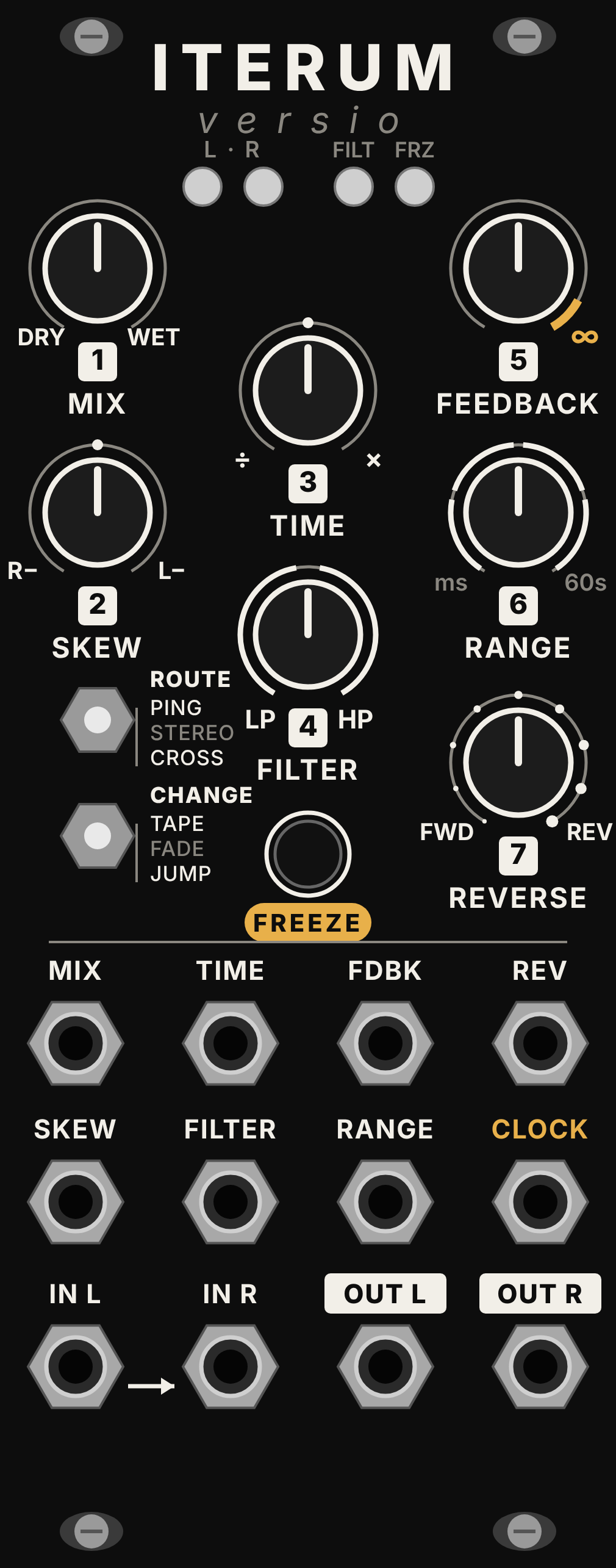
     [1 MIX]      [3 TIME]      [5 FEEDBACK]
     [2 SKEW]                   [6 RANGE]
                  [4 FILTER]
 ABC  ROUTE                     [7 REVERSE]
 XYZ  CHANGE        [FSU] FREEZE        FSU jack = CLOCK
Every knob has a matching CV input (jacks 1–7), summed with the knob.
| # | Control | Free-running | Clocked |
|---|---|---|---|
| 1 | MIX | dry/wet, equal power | |
| 2 | SKEW | bipolar: centre = equal times; left shortens the right channel, right shortens the left channel, down to ½ | 9 steps: ½, ⅔, ¾, ⅞ (right) · equal · ⅞, ¾, ⅔, ½ (left) |
| 3 | TIME | time within the selected range (exponential) | ratio to the clock: 1/16, 1/12, 1/8, 1/6, 1/4, 1/3, 3/8, 1/2, 2/3, 3/4, 1 (noon), 4/3, 3/2, 2, 3, 4, 6, 8, 12, 16 |
| 4 | FILTER | left = low-pass (20 kHz → 500 Hz), centre = off, right = high-pass (20 Hz → 1.2 kHz). It sits inside the feedback loop, so each repeat is filtered again | |
| 5 | FEEDBACK | 0–110 %. Above 100 % the repeats build up and are held by soft saturation | |
| 6 | RANGE | 4 zones: 5–100 ms · 50–600 ms · 0.3–3 s · 1.5–60 s | shifts the TIME ratios by octaves: ÷4, ÷2, ×1 (noon), ×2 |
| 7 | REVERSE | first 10 % of travel = always forward, last 10 % = always reversed. In between, each repeat is reversed with a probability that grows with the knob |
ABC — ROUTE
- A · Ping-pong: the input is summed to mono and enters on the left, then bounces L → R → L
- B · Stereo: two independent delay lines
- C · Cross: stereo input with cross-coupled feedback (ping-pong that keeps the stereo image)
XYZ — CHANGE (how time changes are handled)
- X · Tape: like a tape machine, changing the time repitches the repeats
- Y · Fade: 60 ms crossfade to the new time, no pitch change
- Z · Jump: near-instant (3 ms) switch, good for glitches and stutters
FSU
- Jack: external clock. The period is measured between rising edges and averaged, so small clock jitter does not disturb the repeats; real tempo changes are followed at once. The last tempo is kept if the clock stops: the module stays in clocked mode (cyan LEDs) until you hold the button
- Button: toggles freeze. The buffer is looped at the current delay length (up to 60 s); input and feedback are muted. TIME, CHANGE and REVERSE keep working on the frozen material, the filter only affects the output
- Button held 1.5 s: back to free-running time (the freeze state is left unchanged)
In 1 is normalled to In 2: patch a single cable into In 1 for a mono source.
LEDs (left to right)
- Left repeats — 2. Right repeats: each blinks when a repeat arrives on its side. White = forward (free-running), cyan = forward (clocked), violet = reversed. When clocked, blinks are locked to the incoming clock. Below 100 ms the repeats are too fast to blink, so the LEDs stay steadily lit
- Filter: orange = low-pass, light blue = high-pass, brighter as it closes; off at centre
- Status: solid red = freeze, pulsing red = feedback above 100 %
LED brightness: hold the FSU button while powering the case on to cycle between bright, dim and off. All four LEDs confirm the new level for one second (a short red blink means "off"). The setting is saved and kept across power cycles.
Installing
A prebuilt binary is in firmware/IterumVersio.bin.
- Connect the Versio to your computer via the USB port of the Daisy Seed on the back of the module.
- Put the Seed in DFU mode: hold BOOT, press and release RESET, then release BOOT.
- Flash it with the Electro-Smith Web Programmer (Chrome/Edge), or with
make program-dfuafter building from source (see BUILD.md).
Before flashing, make sure you have a copy of the original Noise Engineering firmware so you can go back at any time.
Building from source
See BUILD.md for the toolchain, the libraries, how to compile and flash, and how to adjust the knob and switch mapping.
Panel
The panel/ folder contains the panel artwork:
iterum_versio_panel.svg— preview with knobs, jacks and switches drawn initerum_versio_panel_print.svg— artwork only, with hole positions as red guidesmake_panel.py— the Python script that generates both (no dependencies)
The SVG is drawn at real 10HP size (50.5 × 128.5 mm). Hole positions were measured from a photo of a Versio panel: check them against a real panel before having one made.
Technical notes
- 48 kHz, 32-sample blocks, CPU at 480 MHz
- Buffers: 2 × 4,194,304 float samples in SDRAM (32 of 64 MB)
- Forward reads use 4-point Hermite interpolation. In Tape mode the time follows the knob with ~250 ms slew and the "tape speed" is limited between −3× and +5×
- Reverse: two overlapping grains with a sin² window, each as long as the delay; each grain plays the just-recorded segment backwards
- Feedback path: DJ filter (2-pole TPT state-variable filter, Butterworth response), DC blocker, soft saturation
- Output: equal-power mix with extra headroom around noon, then a stereo-linked peak limiter (instant attack, 150 ms release, about −1 dBFS) and a gentle safety clip
- TIME and SKEW are smoothed (20 ms) and pass through a deadband, so pot and CV noise never moves a delay that should be standing still
- The LED brightness setting is stored in the last 4 KB sector of the QSPI flash
- LEDs use libDaisy's software PWM, updated 4000 times per second
Changes
See CHANGELOG.md.
License
MIT. libDaisy and DaisySP are © Electro-Smith and released under the MIT license.