Hagiwo MOD1 firmwares
Alternative firmwares for Hagiwos Mod1 Arduino based Module. https://note.com/solder_state/n/nc05d8e8fd311
Mod1 is an Arduino Nano based eurorack module designed by Hagiwo, that can be utilized with own code.
Here you will find some slightly changed or completely new code ideas for this module.
Project by Rob Heel 2025 and ongoing.

Firmware online flasher
I made a website, where you can flash these firmwares directly from a browser (Chrome or Edge), if you do not want to tinker with the ino files. https://robertheel.com/content/mod1firmwareflasher/
Current firmwares
-
Enhanced Bernoulli Gate and Loop Sequencer with glitch bursts
-
Turing machine/ Klee style sequencer with quantized/ unquantized CV out
-
Procedurally Generated Triple Wavetable LFO
Chaos, Neuroscience & Complex Systems Models Disclaimer
Mod1 LFO
Multi waveform LFO.
Instead of SawRevWave a random slope is used as 5th waveform.
SawRevWave is still in the code if you want to return to Hagiwos original code.
Selectable waveforms: Sine, Triangle, Square, Saw, Random Slope, MaxTable waveforms.
- Pot1 → frequency
- Pot2 → waveform select
- Pot3 → output level
- F1 → frequency CV in
- F2 → waveform CV in
- F3 → output level CV in
- F4 → output
- BUTTON → change frequency range
- LED → output
- EEPROM → Saves the frequency range when the button is pressed Back to firmware list
3chan LFO
Three channel LFO.
Added a fourth waveform: Random slope.
Selectable waveforms: Triangle, Square, Sine, Random Slope chosen by a push button on D4.
- Pot1 → LFO1 frequency
- Pot2 → LFO2 frequency
- Pot3 → LFO3 frequency
- F1 → frequency CV in (apply to all ch LFO freq)
- F2 → LFO1 output
- F3 → LFO2 output
- F4 → LFO3 output
- BUTTON → change waveform
- LED → LFO1 output
- EEPROM → Saves select waveform Back to firmware list
randomwalk
Random Walk with Gravity Mode + Lagged Output
Button toggles between classic Random Walk mode and Gravity Mode.
Gravity Mode pulls the output slowly back to 0 over time.
F2 outputs a lagged/delayed version of F4, great for ambient crossfading effects.
The lagged version creates beautiful dancing relationships with F4, when modulated via CV in.
Slow, evolving CV signals, offering both chaotic and stabilized output behaviors.
Rate, Bias/Offset, ChaosDepth can be controlled via pots.
Classic Random Walk Mode: Generates smooth, random CV output with adjustable step size.
Gravity Mode: Adds a gradual pull back to zero, creating a drifting, self-centering effect.
- Pot1 → Rate / Control the frequency of random steps.
- Pot2 → Bias/Offset /Shifts the output up or down.
- Pot3 → ChaosDepth (step size of walk) / Adjust the step size from subtle drifts to wild jumps.
- Button → switch mode
- F1 → CV input controls Lag Amount - how closely F2 follows F4. Perfect for LFO modulation!
- F2 → CV output/ Lagged CV out
- F3 → CV input / adds to ChaosDepth
- F4 → Random Walk Output Back to firmware list
bezier curve with spike jitter mode
Bezier curve random CV generator by Hagiwo adapted for Mod1 and added a second Spike/Jitter Bezier mode, accesible via button.
Smooth random CV source with additional spike and jitter mode.
Spike, jitter probability and spike length can be fine tuned in code. I think i settled for nicely erratic not too random values in the spike mode.
- Pot1 → freq
- Pot2 → curve
- Pot3 → dev
- F1 → freq CV in
- F2 → curve CV in
- F3 → dev CV in
- F4 → output
- LED → Pin 3
- Button → switch modes Back to firmware list
sample and hold with slew
Classical sample and hold function. Sample and hold output on F4, triggered by button or F1 trigger input.
If nothing is patched into sample input F2 an internal sample source is used.
Pot1 is a bias for the internal noise.
In the middle position truly random, fully clockwise shifts towards higher values, fully counter clockwise shifts towards lower values.
Pot3 is gain/ level.
Sample and hold output on F4
Slewed output on F3 with Pot 2 controling time constant of the slew, up to 1000 ms slew.
- Pot1 → A0 noise bias
- Pot2 → A1 time constant slew
- Pot3 → A2 gain
- F1 → A3 trigger in
- F2 → A4 sample input
- F3 → A5 slew output
- F4 → D11 sample and hold output
- LED → Pin 3
- Button → Pin 4 trigger Back to firmware list
Enhanced Bernoulli Gate and Loop Sequencer with glitch bursts
This firmware combines a probabilistic Bernoulli gate with a step sequencer, providing flexible trigger manipulation and glitchy bursts for randomness, controlled probabilities, and rhythmic chaos.
Route incoming triggers to either of the two outputs. The decision is random, with a controllable amount of randomness/ probability (pot1 + CV input).
In Step Sequence Modes, pressing the button generates a new randomized sequence. 4-Step, 8-Step, 32-Step Sequence.
With pot3 you can introduce Miss Probability and Glitch Bursts.
This combination of probability control, step sequencing, trigger skipping, and glitch bursts makes the module versatile for generative rhythms, random variations, and chaotic textures.
Controls:
Pot 1 Probability
Sets the probability of switching between the two outputs (F3 and F4).
Fully counterclockwise: Always output F3.
Fully clockwise: Always output F4.
Intermediate positions introduce a random chance of either output based on the pot setting.
Pot 2 Mode/Length
Selects between Bernoulli Mode and Step Sequence Modes:
0-20% (CCW): Bernoulli Mode
20-40%: 4-Step Sequence
40-60%: 8-Step Sequence
60-80%: 16-Step Sequence
80-100% (CW): 32-Step Sequence
In Step Sequence Modes, pressing the button generates a new randomized sequence.
Pot 3 Miss Probability and Glitch Burst
Sets the probability of skipping triggers:
Fully counterclockwise: No triggers are missed.
Turn clockwise: Up to 35% of triggers are missed. Linear 0-35%.
80-100% (CW): Introduces Glitch Bursts, where rapid chaotic trigger sequences are generated occasionally.
Inputs and Outputs:
F1 Trigger Input
Incoming trigger signal to be processed through the Bernoulli gate or sequencer.
F2 CV Input
Modulates the output probability in conjunction with Pot 1, allowing CV control.
F3 Output 1
One of the two output trigger channels, chosen based on the current probability setting.
F4 Output 2
The second output trigger channel, acting as a counterpart to F3.
Button
Pressing the button in Sequence Mode regenerates the step sequence with a new randomized pattern.
In Bernoulli Mode, the button has no effect.
LED Indicator
Flashes on every valid trigger output (either F3 or F4).
Back to firmware list
pot1 recorder
Pot1 Recorder with Fast PWM Output (100 Hz S&H style) max recording time 7.5 sec. S&H style recording and playback in order to squeeze out a useful recording time of the nano’s small SRAM.
You can record movement of pot1 while holding down the button. Once let go it will loop the recording.
Pot2 is speed, from half to double speed.
Pot3 is gain control.
Speed CV offset via F1 CV in.
Gain CV offset via F2 CV in.
CV out on F4.
- Pot1 → Pot to record
- Pot2 → Speed control of recording
- Pot3 → Output gain
- F1 → Speed offset CV in 0-5 V
- F2 → Gain offset CV in 0-5 V
- F3 → /
- F4 → Output
- LED → Visualize Output
- Button → Recording button Back to firmware list
Turing Machine Klee-style sequencer with quantized and unquantized CV out
This firmware turns your Mod1 into a Turing Machine / Klee-style sequencer with quantized and unquantized CV out.
It generates evolving or locked step sequences using a shift register, modulated by a randomness knob and/ or CV with slip, lock, and random modes.
Loop length and output range are controllable via pots.
Musical scales are selectable via a button for the quantized output; Major, Minor, Phrygian.
Great for random, looped and evolving melodies and patterns.
Pot1 → Main sequencing pot (random/ slip/ lock)
At noon, the sequences are random.
At 5 o'clock, it locks into a repeating sequence.
At 7 o'clock, it double locks into a repeating sequence twice as long as the 'length' setting.
At 3 o'clock or 9 o'clock, it slips; looping but occasionally changing notes.
Pot2 → Loop length
Pot3 → Range/ gain
F1 → Trigger in
F2 → CV in offset for pot1
F3 → Quantized CV output
F4 → CV output
BUTTON → change scale for quantized output
Back to firmware list
Dual AD envelope
Two independent Attack–Decay envelopes with shared attack and release knobs.
Per-envelope random timing variation via Pot3 (A2):
• Fully CCW → no variation
• Fully CW → max random deviation per trigger
Variations are stronger at shorter attack/release settings, lighter at longer ones.
Envelope 1 is also manually triggerable via push button.
LED indicates envelope 1 level.
Outputs are fast PWM (16-bit for ENV1/ENV2, 8-bit LED).
Designed for Eurorack/modular trigger input and CV envelope output.
- Pot1 → attack
- Pot2 → decay
- Pot3 → variation amount
- F1 → trigger in envelope1
- F2 → envelope1 out
- F3 → trigger in envelope2
- F4 → envelope2 out
- BUTTON → trigger envelope1
- LED → output envelope1 Back to firmware list
Procedurally Generated Triple Wavetable LFO
Triple wavetable / terrain LFO with CV speed modulation input and probabilistic SloMo mode.
On each button press, three independent wavetables (“terrains”) are generated.
Pot C controls the number of “knots” (points) in each waveform. Individual outs on F2, F3, F4.
Waveform generation is semi-random, following musical constraints:
-
Starts and ends at the same value for seamless looping.
-
Contains at least one zero crossing.
-
Nonlinear knot spacing.
-
After a spike, a longer rest region follows.
-
One curved segment per waveform (Bézier)
Wavetables reading has a defined detune in speed:
speed1 * 0.9 -> F2; speed2 * 1.0 -> F3; speed3 * 1.1 -> F4;
Random slow-mo events that scale with tempo - probability set via Potb.
SloMo randomly and independently slows down the playback speed of each terrain waveform for a short, speed-dependent duration — creating natural, unsynced pauses or “breaths” in their motion.
This is my fav LFO for soundscape compositions currently, the three outputs align, drift apart and partially resync.
CV input (0 to 5 Volts) on F1 (A3) for speed offset (adds 0–1 Hz to base speed).
Pots:
A0 -> Base speed (0.01–5 Hz)
A1 -> SloMo probability
A2 -> Knots (3..12)
Button:
D4 -> generate new set of waveforms
LED:
D3 -> blink during generation
Outputs:
F2 (D9) : Terrain 1
F3 (D10) : Terrain 2
F4 (D11) : Terrain 3
Inputs:
F1 (A3) : CV input for speed offset (adds 0–1 Hz to base speed)
Chaos, Neuroscience & Complex Systems Models
Some of these models are very musical and great to perform, interact and patch with. Especially Lorenz system does work really well as organic evolving modulation source.
Other firmwares in this section grew probably more of curiosity for unusual modulation models and approaches. In some cases I am still searching for a musical context with specific firmwares.
But i share them here, as personal memorandum and you might built something cool with it or expand on it. There is definitely interesting bits and approaches in this models.
Lorenz System
Lorenz Attractors are great for organic, non-repeating CV movement, chaotic but not random. This system inspired the popular 'butterfly effect' metaphor, where small changes can lead to dramatically different outcomes. This chaos theory based LFO is fantastic for organic non repeating movement. With the three outputs it is very easy to create patches that drift and breathe.

Pots:
A0 → Sigma (flow strength / controls how fast x and y try to equalize/ also mapped to stepSize
A1 → Rho (divergence / higher = stronger pull from center -> more chaos, from calm to chaos)
A2 → Beta (damping / controls how sharply z grows or decays)
Input:
F1 (A3 / D17) → Trigger input (resets attractor on rising edge)
Outputs:
D9 (F2) → x axis (PWM CV)
D10 (F3) → y axis (PWM CV)
D11 (F4) → z axis (PWM CV)
Button (D4) → toggle normal and slow mode
LED (D3) → Blinks in stepsize
Hindmarsh-Rose Model - Neuron Bursting LFO
A 3D neuron model that produces periodic repetitive patterns and bursting based on the Hindmarsh-Rose Model. Can be tricky because small changes of variables (pots) can lead to unexpected results, while in other settings nothing much happens.
If nothing is happening, nudge pot 3 (I) upward slowly — transitions between regimes can be abrupt.
The model has three variables:
- x (membrane potential): Fast spiking variable
- y (recovery): Fast inactivation
- z (adaptation): Slow variable that modulates bursting
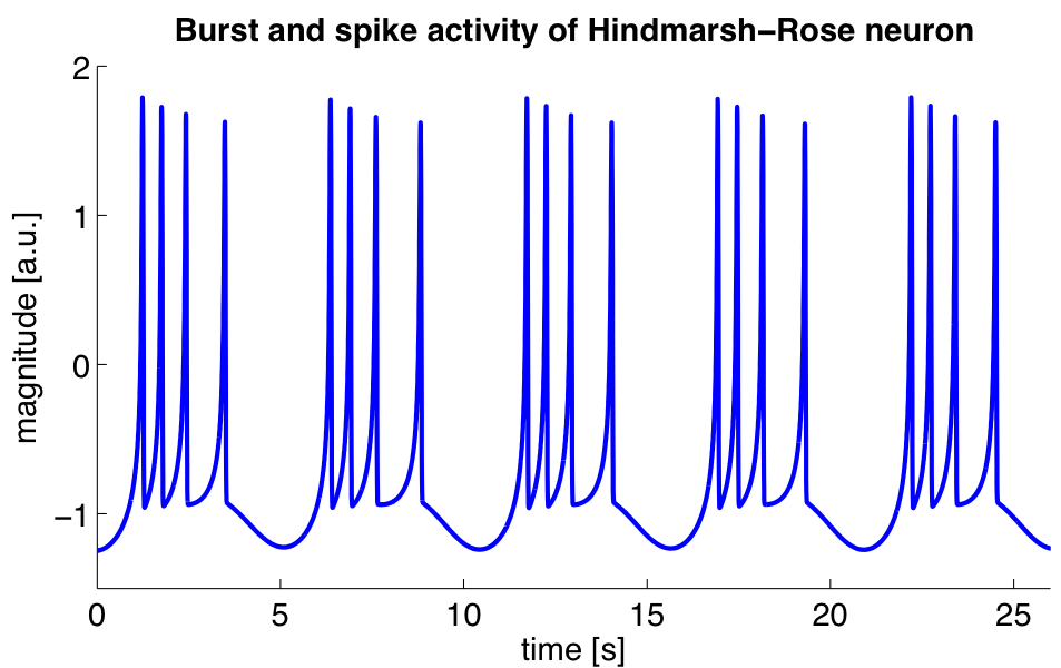
This creates behaviors like: periodic repetitive patterns, spiking and bursting and silence at times. x and y (F2+F3) outputs do interact quite nicely and have a natural rhythmic relationship with each other. z (F4) is better suited as a slow macro-modulator, it can be glacial in timing and movement.
It can take time to move through its phases, long listening can be rewarding.
Basically you might encounter three phases
"Nothing much happens"
The system is sitting at a stable fixed point. Below a threshold of I, x just settles and z slowly climbs to meet it. No oscillation. Changing pot3 (I) or feeding control voltage into F1 should start activity
"Repetitive pattern"
You've crossed into periodic bursting. Repeating patterns can persist at fixed parameters, or gradually disappear as the slow z variable pulls the system back toward silence. When I is being modulated via CV you can deliberatly push and pull the system.
"Dies down"
This is the z (slow adaptation) variable. Eventually it suppresses the oscillation back toward quiescence. It's a slow envelope that the model generates intrinsically.
Pots:
A0 → r (adaptation speed / 0.001-0.01: how quickly the slow variable adapts)
A1 → s (adaptation strength / 1-6: how strongly adaptation affects spiking)
A2 → I (input current / 1-4: drives activity from calm to bursting)
Input:
F1 (A3 / D17) → CV input - modulates input current
Outputs:
D9 (F2) → x (membrane potential - main chaotic spiky output)
D10 (F3) → y (fast recovery - complementary rhythmic output)
D11 (F4) → z (slow adaptation - long evolving wave)
Button (D4) → toggle normal and slow mode
LED (D3) → Blinks on spike peaks
Kuramoto Model - Coupled Oscillator Synchronization LFO
A model of coupled phase oscillators that exhibits spontaneous synchronization. Three oscillators with different natural frequencies try to sync - sometimes they lock,sometimes they drift apart, creating organic evolving patterns.
Kuramoto Model is the model behind firefly synchronization, heart pacemaker cells, and neural rhythms.
Three oscillators with phases θ1, θ2, θ3:
- Each wants to oscillate at its own natural frequency
- Coupling pulls them toward synchronization
- The battle between individuality and conformity creates emergent behavior
Pots:
A0 → Base frequency (0.5-5 Hz: overall speed of oscillations)
A1 → Frequency spread (0-5: how different the natural frequencies are)
A2 → K (coupling strength / 0-3: LOW=locked sync, MID=partial sync, HIGH=independent)
Input:
F1 (A3 / D17) → CV input (modulates coupling strength K, -1 to +2 offset to Pot C)
Outputs:
D9 (F2) → Oscillator 1 (sine wave from phase θ1)
D10 (F3) → Oscillator 2 (sine wave from phase θ2)
D11 (F4) → Oscillator 3 (sine wave from phase θ3)
Button (D4) → Toggle between sine and square wave outputs
LED (D3) → Blinks when oscillators are synchronized (phase coherence indicator)
Izhikevich Neuron Model - Neuron Spiking LFO
A computationally efficient model that reproduces 20+ different neuron firing patterns.
The model has two variables:
- v (membrane potential): Fast spiking variable
- u (recovery variable): Slow adaptation variable
Four parameters (a, b, c, d) control the neuron's "personality":
- a: recovery time scale (how fast u recovers)
- b: sensitivity of u to v (coupling strength)
- c: after-spike reset value for v
- d: after-spike reset increment for u
Pots:
A0 → a (recovery speed / 0.01-0.2: faster recovery = different spike patterns)
A1 → b (sensitivity / 0.1-0.3: changes spike clustering behavior)
A2 → I (input current / 0-15: drives activity from rest to chaos)
Input:
F1 (A3 / D17) → CV input (modulates input current I, -5 to +10 offset to Pot C)
Outputs:
D9 (F2) → v (membrane potential - main spiky chaotic output)
D10 (F3) → u (recovery variable - slower complementary wave)
D11 (F4) → spike gate (HIGH during spike, LOW otherwise). Biological timing rather than metronomic timing. Irregular but not random.
Button (D4) → Cycle through neuron types (Regular/Chattering/Bursting/Fast Spiking)
LED (D3) → Shows neuron type: 1 blink=Regular, 2=Chattering, 3=Bursting, 4=Fast
mod1 general Hardware Configuration
Potentiometers
- Pot1 → A0
- Pot2 → A1
- Pot3 → A2
Inputs/Outputs:
-
F1 → A3/ D17 in/output
-
F2 → A4/ D9 in/output
-
F3 → A5/ D10 in/output
-
F4 → D11 in/output
-
LED → Pin 3
-
Button → Pin 4