Free Modular Quantizer — Alternative C++/PlatformIO Firmware







An independent alternative firmware for the Free Modular Quantizer Eurorack module, written in modern C++17 for PlatformIO and the original Arduino Nano / ATmega328P at 16 MHz hardware.
It keeps the module recognizably the same instrument: the original pin mapping, panel controls and core quantizer workflow remain intact. The implementation focuses on easier builds, stronger testability and persistence, hardware calibration, well-defined edge-case behavior and an additional performance-oriented Arpeggiator layer.
[!NOTE] Status: The latest declared release is 0.2.1. Changes described under
Unreleasedare development work intended for the next release; they are not a published 0.2.2 release yet. The current development tree separates normal production firmware from a dedicated calibration/maintenance image while sharing the same persistent analog profile.
Acknowledgement — Quinn Freedman
This project exists because of Quinn Freedman's original Quantizer design and Rust firmware.
The original design makes a particularly pragmatic set of choices: it is cost-conscious, approachable, uses readily understandable building blocks and avoids unnecessary hardware complexity. For DIY use, that balance is unusually strong. The module is comparatively straightforward to build, easy to study and well suited to modification without requiring an expensive or highly specialised platform.
That makes the original Quantizer more than just a reference implementation for this repository: it is a very good example of hardware that invites experimentation. This C++ reimplementation is intended to respect that character rather than replace or diminish it.
Original project references:
- Free Modular Quantizer project page: https://freemodular.org/modules/Quantizer/
- Original Quantizer source, firmware, documentation, and KiCad files: https://github.com/QuinnFreedman/modular/tree/main/modules/Quantizer
- Shared Rust
fm-libused by the original firmware: https://github.com/QuinnFreedman/modular/tree/main/fm-lib
This repository is an independent reimplementation and is not an official Free Modular repository.
Contents
- Why this alternative firmware exists
- What this firmware adds
- Using the firmware
- User manual
- Firmware installation and updates
- Quantization at a glance
- Normal display
- Main controls
- Quantizer SHIFT shortcuts
- Track-and-Hold and Sample-and-Hold
- Channel interaction
- Discrete channel LEDs
- Scalar menus
- Save/load and factory presets
- Arpeggiator layer
- LED brightness calibration
- Startup fade
- Version history
- Technical reference
Why this alternative firmware exists
The original Rust firmware is compact and closely tied to the module it was written for. That is part of its appeal. For continued maintenance and experimentation, however, its AVR Rust setup also comes with a relatively specialised toolchain: it relies on a nightly compiler and unstable features, and parts of the original source contain a compiler-specific inline-assembly workaround. Reproducing and maintaining that environment is less convenient today than using the conventional Arduino/AVR tooling available through PlatformIO.
This project therefore takes a different engineering route while retaining the original hardware and interaction concept. The goals are practical:
- straightforward builds and uploads on Windows, Linux and macOS;
- a familiar Arduino-compatible C++17 toolchain for the ATmega328P;
- host-side unit, integration, regression and system tests without requiring AVR hardware for every change;
- native AVR builds and resource-budget checks in GitHub Actions;
- clear separation between quantizer logic, application/UI code, persistence and board support;
- easier diagnostics and instrumentation during development, plus a panel-driven maintenance workflow for hardware calibration and output verification;
- centralised configuration of timing, analog assumptions, LED behavior and calibration;
- a lower maintenance barrier for contributors already familiar with Arduino and PlatformIO;
- robust, validated persistence instead of treating arbitrary or interrupted EEPROM data as valid state;
- explicit fixes for a small number of edge cases verified in the original implementation;
- room for additional features that fit the existing front panel without requiring hardware changes.
The original firmware remains the behavioral and hardware reference wherever that behavior is intentional and useful. This is deliberately not a line-by-line translation: compatible behavior is preserved where appropriate, known defects are not intentionally reproduced, and extensions are documented explicitly.
What this firmware adds
The original firmware already provides the essential instrument: two independent quantizer channels, twelve-note scale editing, Track-and-Hold and Sample-and-Hold, Glide and delay, pre-/scale-/post-shift, Channel-B Relative/Absolute operation, channel linking, and twelve scale plus twelve full-configuration memory slots. Those are core Free Modular Quantizer features and are retained here rather than presented as additions.
This alternative firmware adds or deliberately changes the following:
- Arpeggiator performance layer: a complete second operating layer with internal FREE timing, external CLOCK/RESET operation, clock ratios, patterns, scale-aware shapes, adjustable length and octave range, swing and optional per-step triggers.
- Fast, symmetrical layer switching: double-click SHIFT to enter the Arpeggiator layer and double-click SHIFT again to disable it and return to the Quantizer. No hardware changes or additional controls are required.
- Built-in factory preset bank: empty full-configuration slots expose twelve useful factory scales; saving a user configuration to a slot transparently overrides its factory fallback.
- Live-state restore: the working state can be restored after power cycling, including both channel configurations, Arpeggiator settings, selected channel and active UI layer.
- More robust EEPROM persistence: records are versioned, CRC-checked and range-validated, and writes are handled asynchronously rather than accepting a slot solely because a sentinel byte is present.
- Persistent per-channel analog calibration: independent ADC and DAC offset/gain correction for Channels A/B is loaded from a redundant CRC16 EEPROM journal, with
AnalogConfig.has factory fallback. A separate maintenance firmware image performs guided five-point 1/3/5/7/9 V ADC least-squares fitting with independent 0/2/4/6/8 V verification and verifiedCV OUT → CV INDAC self-calibration entirely from the existing front panel. The production image contains no calibration writer or command shell; it only reads and applies the stored profile. A compact generation-bound qualification record can later be printed over USB as a read-only calibration report/label.
[!NOTE] Analog calibration is not routine maintenance. Use the maintenance image only for a module that has never been individually calibrated, after calibration data have been erased/lost, after relevant analog-path hardware changes, or when measured pitch / 1 V/oct performance indicates a problem. A normal EEPROM-preserving firmware update does not require recalibration.
[!CAUTION] Never connect the normal Eurorack bus and Nano USB at the same time. Flash the maintenance image with the Eurorack ribbon disconnected, then disconnect USB completely and perform the actual calibration under normal Eurorack
+12 V / -12 V / +5 Vpower. For the stored report or the production-image flash, power the case off, disconnect the ribbon, and reconnect USB.
The maintenance image is panel-driven: SAVE starts the full wizard, LOAD verifies an existing calibration, SHIFT + SAVE runs ADC-only calibration, and SHIFT + LOAD runs DAC/self-calibration only. Within a wizard, SAVE confirms the current wiring/voltage step and LOAD cancels safely. The odd-voltage note LEDs C#/D#/F/G/A guide the 1/3/5/7/9 V fit points; C/D/E/F#/G# then guide the independent 0/2/4/6/8 V verification points. The bench PSU is only the adjustable source; the DMM reading at the jack adapter is the calibration reference.
Hold SHIFT for one second from maintenance idle to enter Output Test. With a stored profile it starts in calibrated (CAL) mode; SAVE + LOAD toggles to RAW, which bypasses all stored/factory DAC correction so the two physical output-stage trimmers can be pre-adjusted before software calibration. RAW is shown amber; CAL is green for A and red for B. Holding SHIFT + SAVE + LOAD for five seconds arms a separate destructive erase for calibration/qualification data only; a pulsing red ring requests SAVE confirmation or LOAD cancel. User presets and live musical state are not erased. The channel IN/OUT status LEDs identify the active path or required loopback. Three amber flashes followed by steady dim amber identify maintenance idle; analog acquisition turns the ring off; two green/red flashes indicate ordinary PASS/FAIL and three green/red flashes indicate final qualification PASS/FAIL.
For ADC calibration, the bench supply is only the adjustable voltage source: the DMM reading at the actual jack adapter is the reference. Do not capture a point from the power supply's displayed value alone. General-purpose bench supplies may be accurate enough as sources while their set/readback display is still several millivolts away from the required calibration value.
See README_CALIBRATION.md for the complete illustrated calibration and safety procedure.
- On-device LED color calibration: red and green brightness can be adjusted independently over the TLC5947 range while green, red and amber are shown together for direct visual balancing.
- Improved power-on behavior: the default scale is chromatic, the final enabled scale note is protected against accidental removal, and the
Unreleaseddevelopment tree uses one compact <=750 ms green→amber→red startup fade before restoring the actual UI frame. - Corrected edge cases from the reference implementation: verified issues such as Track-and-Hold with delay, negative scale shifts, full-scale ADC mapping and interrupted/invalid persistence are handled explicitly; the detailed comparison is documented below.
The implementation itself also differs substantially: it uses a conventional C++17/PlatformIO AVR toolchain, portable host-side tests, AVR CI builds and explicit flash/SRAM resource gates. These engineering changes are primarily about maintainability and reproducibility rather than changing the front-panel instrument.
The module still uses the original hardware. No PCB, component or wiring modification is required or supported by this firmware project.
Using the firmware
User manual
The dedicated end-user manual workspace is prepared under docs/manual/. The editable manual source is intended to be maintained as a LibreOffice Writer document and uses the Ubuntu Font Family as a required editing dependency. Manual-specific licensing and font setup information are kept with the manual sources so the firmware licence and documentation licence remain clearly separated.
The sections below provide the essential front-panel reference directly in the repository README.
Firmware installation and updates
For a prebuilt release HEX file, follow the dedicated firmware installation/update guide. It covers safe rack removal, mandatory disconnection from the Eurorack power bus, USB-only flashing, old/new Nano bootloaders, EEPROM-preserving updates, recovery, and the required post-flash startup check. Windows 11 users can follow the separate AVRDUDESS step-by-step guide, including the numbered application screenshot.
[!CAUTION] Do not connect USB to the module while it is still connected to the Eurorack power bus. Power the case off, remove the module, and disconnect the Eurorack ribbon cable first.
Quantization at a glance
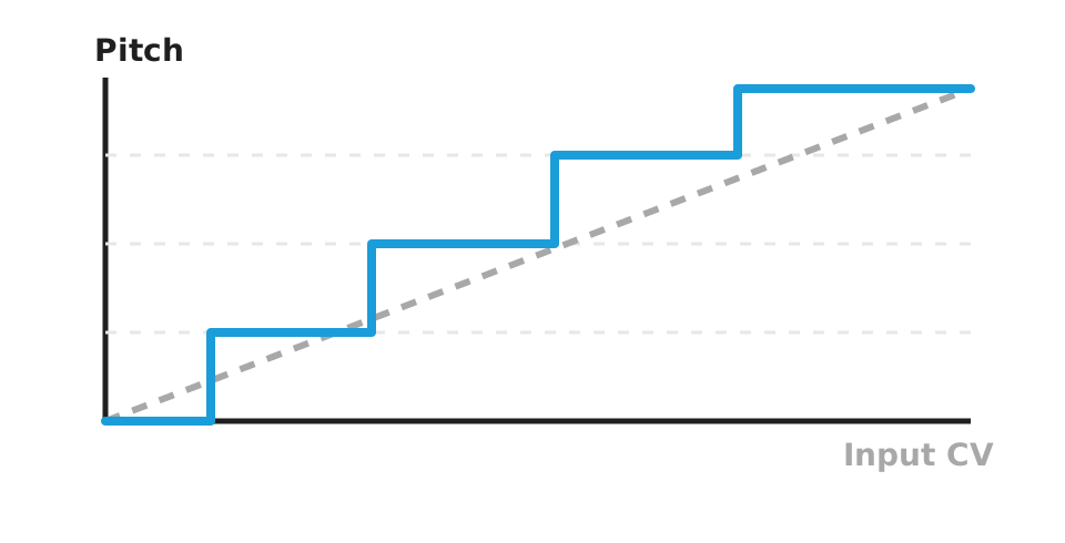
A quantizer maps a continuous input voltage to the nearest pitch that is currently allowed by the selected scale. The scale therefore determines the available steps; the input CV still determines where on that staircase the output lands.
Normal display
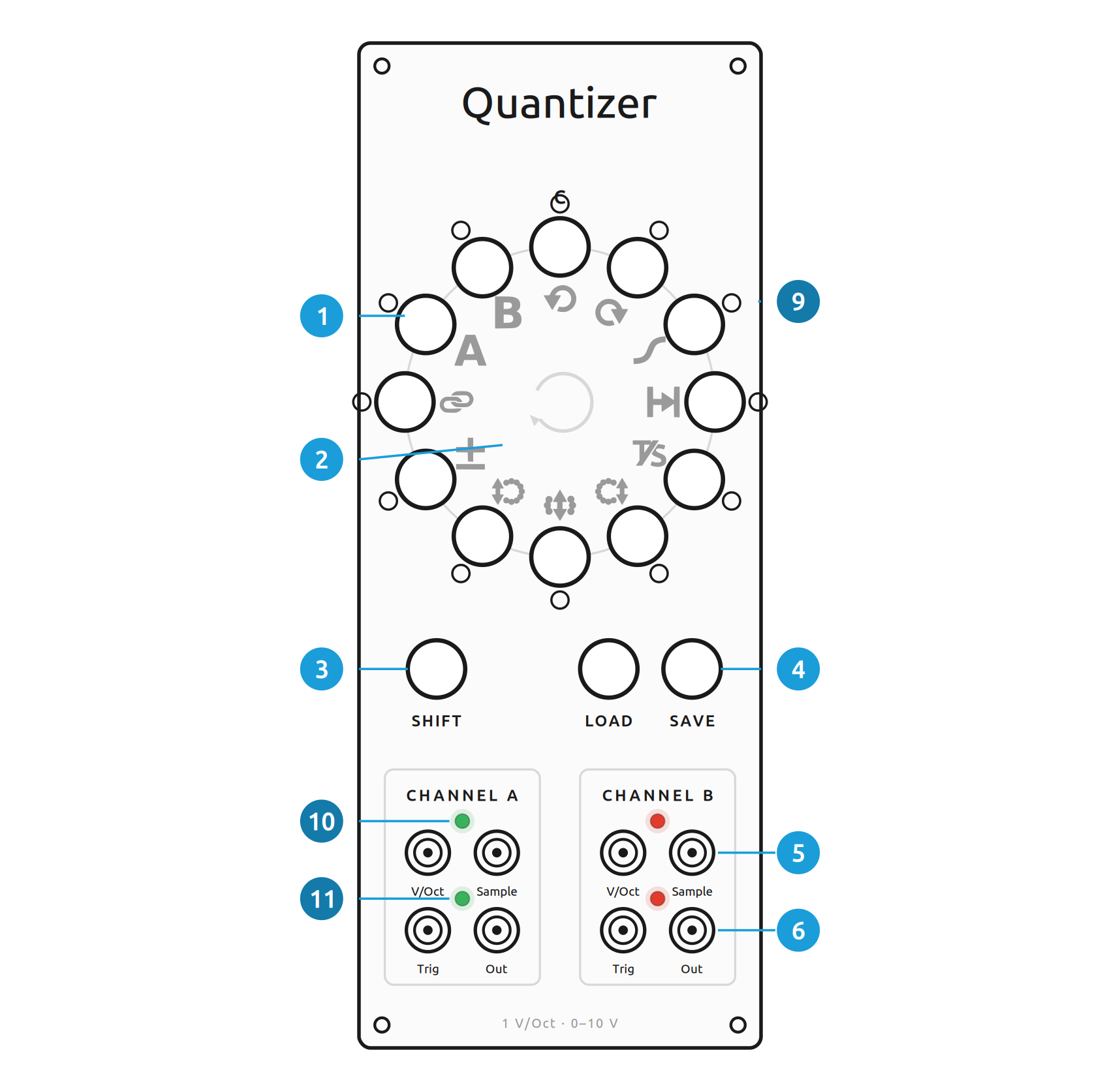
The twelve note buttons are indexed 0–11 clockwise, with index 0 at the 12 o'clock / C position.
- Channel A: green
- Channel B: red
- Current quantized note: amber overlay
- Linked channels: shared scale amber; current A/B notes green/red
The factory scale is chromatic, so a freshly flashed module is immediately usable. The firmware prevents the final active note of a scale from being disabled accidentally.
Main controls
| Control | Function |
|---|---|
| Note 0–11 | Toggle the corresponding pitch class in the selected scale |
| SAVE | Select a scale-save slot |
| LOAD | Select a scale-load slot |
| SHIFT + SAVE | Select a full-configuration save slot |
| SHIFT + LOAD | Select a full-configuration load slot; user data takes priority, otherwise factory preset |
| LOAD + SAVE, hold 2 s | Erase all user save slots |
| SHIFT + LOAD + SAVE, hold 5 s | Enter LED brightness calibration |
| SHIFT, double-click | Switch Quantizer ↔ Arpeggiator layer; entering enables the selected Arpeggiator and flashes the ring green twice, returning disables all Arpeggiators and flashes red twice |
A SHIFT double-click is deliberately symmetrical: double-click to enter, double-click again to leave. Both clicks must be short; the second press must begin within 350 ms of the first release. Ordinary SHIFT + note, SHIFT + SAVE and SHIFT + LOAD gestures remain normal modifiers and do not trigger a layer change.
Quantizer SHIFT shortcuts
The symbols below match the function pictograms used for the module documentation and panel reference.
| Symbol | Combination | Function | Feedback |
|---|---|---|---|
 | SHIFT + 0 | Rotate scale one step left | updated scale |
 | SHIFT + 1 | Rotate scale one step right | updated scale |
 | SHIFT + 2 | Glide | scalar display |
 | SHIFT + 3 | Trigger delay | scalar display |
 | SHIFT + 4 | Toggle Track-and-Hold / Sample-and-Hold | green = Track, red = Sample |
 | SHIFT + 5 | Post-shift | signed scalar display |
 | SHIFT + 6 | Scale-degree shift | signed scalar display |
 | SHIFT + 7 | Pre-shift | signed scalar display |
 | SHIFT + 8 | Channel-B Relative / Absolute mode | green = Relative, red = Absolute |
 | SHIFT + 9 | Link / unlink channels | green = linked, red = unlinked |
 | SHIFT + 10 | Select Channel A | A / green |
 | SHIFT + 11 | Select Channel B | B / red |
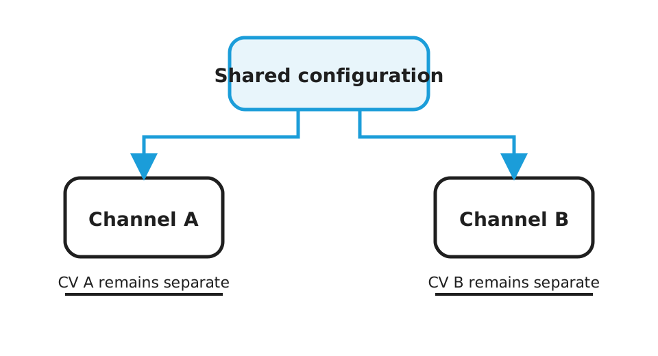
When channels are linked, edits apply to both channels. Linking copies Channel A's current configuration to Channel B and returns selection to Channel A.
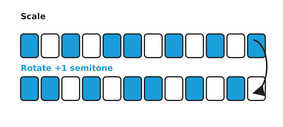
Scale rotation
Scale rotation moves the enabled pitch classes around the twelve-note ring. It does not add a fixed CV offset; the set of pitches available to the quantizer changes instead.
Track-and-Hold and Sample-and-Hold
The factory mode is Track-and-Hold, matching the original firmware.
Track-and-Hold
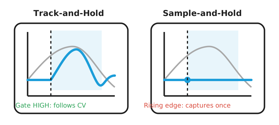
While the trigger/sample input is HIGH, the CV input is followed continuously and re-quantized. When the input goes LOW, the last quantized value is held.
Because the original hardware normalises an empty trigger jack to HIGH, this behaves like a normal continuously running quantizer when nothing is patched to the trigger/sample input.
Sample-and-Hold
Only a LOW→HIGH transition samples the CV input. The resulting quantized value is held until the next rising edge.
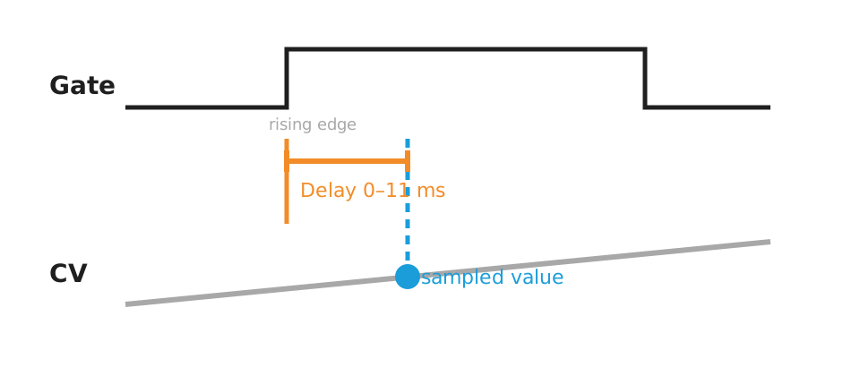
Trigger delay
The configured 0–11 ms trigger delay moves the sampling instant after the rising edge. In Track-and-Hold it delays the start of tracking for that HIGH phase; in Sample-and-Hold it delays the single captured sample.
Mode feedback
SHIFT+4 changes the mode first and then reports the new state on ring position 4:
- green = Track-and-Hold
- red = Sample-and-Hold
After a fresh boot, the first SHIFT+4 changes Track → Sample and therefore shows red. The next press changes Sample → Track and shows green.
Channel interaction
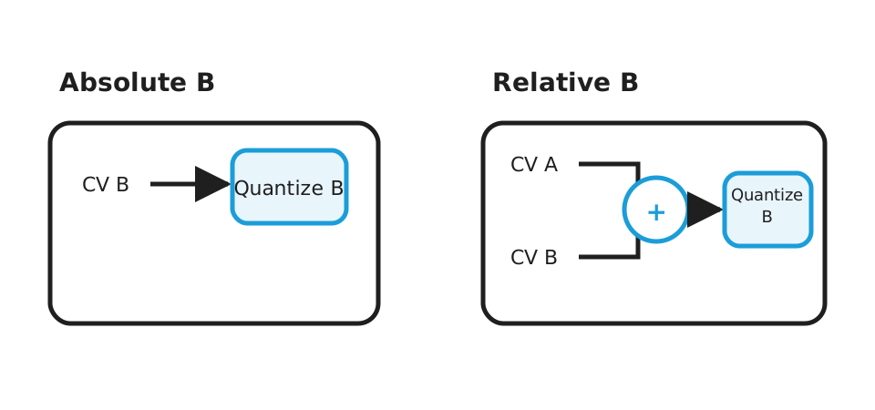
Channel A always quantizes its own CV input. Channel B can either quantize its own input (Absolute) or quantize the sum of A + B (Relative). The sum is clamped to the supported input range before quantization.
Linking is a configuration relationship, not an electrical summing mode. Linked channels share the same scale and channel settings while their CV signal paths remain separate.
Discrete channel LEDs
The four separate LEDs are runtime activity indicators rather than persistent Track/Sample status lights.
| LED | Meaning |
|---|---|
| Input A | Trigger/sample activity on Channel A |
| Output A | Quantized-note change on Channel A |
| Input B | Trigger/sample activity on Channel B |
| Output B | Quantized-note change on Channel B |
With the original HIGH-normalised trigger inputs:
- Track-and-Hold + no trigger cable → Input LED remains on;
- Track-and-Hold + external gate HIGH → Input LED remains on while the gate is HIGH;
- Sample-and-Hold → Input LED flashes on the rising edge and then extinguishes even if the gate remains HIGH;
- Output LED lights briefly whenever the channel changes to a different nominal quantized note.
The physical trigger output pulse is intentionally shorter than the visual LED pulse.
Scalar menus
Glide and Trigger Delay use an unsigned 0–11 representation.
Pre-shift, Scale-shift and Post-shift use a signed representation:
- center/reference position: amber
- positive values: green clockwise
- negative values: red from the upper end of the ring
Pressing a note button selects the displayed value.
Pitch-processing order
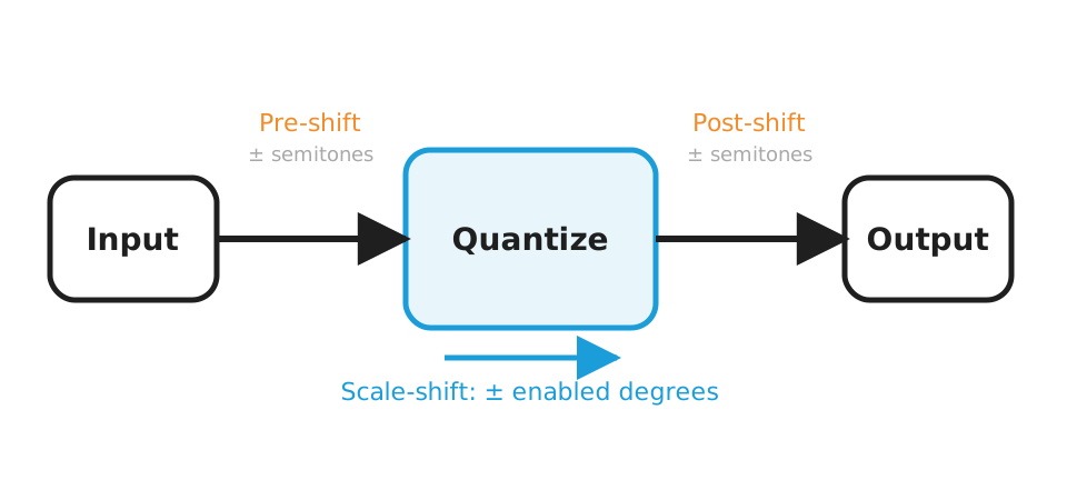
The three shift operations intentionally act at different points in the pitch path: Pre-shift changes the value before quantization, Scale-shift walks through enabled scale degrees after quantization, and Post-shift adds chromatic semitones to the quantized result. Glide then moves the actual output toward that final target.
Glide
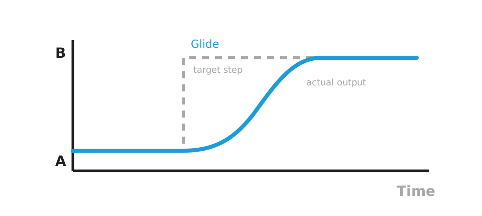
Glide does not change which discrete target note was selected. It smooths the CV transition from the previous output toward the new target; trigger generation remains tied to the discrete target-note change rather than the intermediate DAC steps.
Save/load and factory presets
Normal SAVE/LOAD stores or recalls only the active scale. SHIFT+SAVE and SHIFT+LOAD use the twelve full-configuration slots. A full configuration means the complete musical setup: both Quantizer channel configurations, channel linking, Channel-B Absolute/Relative mode, both complete Arpeggiator configurations including enable state, the selected channel, and the active Quantizer/Arpeggiator UI layer.
Every full-config load position remains useful even before the user has saved anything:
- a valid user configuration in the selected slot is loaded first;
- if the slot is empty, erased or invalid, the corresponding built-in factory preset is loaded;
- saving to that slot transparently overrides the factory fallback;
- erasing user data reveals the factory preset again;
- factory presets are firmware data and are never written into EEPROM simply to initialise the module.
Factory preset bank
| Slot | Preset | Notes |
|---|---|---|
| 1 | Chromatic | C C# D D# E F F# G G# A A# B |
| 2 | Major / Ionian | C D E F G A B |
| 3 | Natural Minor / Aeolian | C D Eb F G Ab Bb |
| 4 | Harmonic Minor | C D Eb F G Ab B |
| 5 | Melodic Minor | C D Eb F G A B |
| 6 | Dorian | C D Eb F G A Bb |
| 7 | Phrygian | C Db Eb F G Ab Bb |
| 8 | Lydian | C D E F# G A B |
| 9 | Mixolydian | C D E F G A Bb |
| 10 | Major Pentatonic | C D E G A |
| 11 | Minor Pentatonic | C Eb F G Bb |
| 12 | Blues | C Eb F F# G Bb |
The factory presets are rooted on C and otherwise use the normal factory Quantizer configuration for both channels. Their Arpeggiator state uses the documented Arpeggiator defaults and starts disabled.
Arpeggiator layer
The Arpeggiator is an official second performance layer rather than a hidden shortcut. Its default produces the rapid scale-aware pitch cycling associated with classic 8-bit home computers and game music, but the same engine can also run with external clock ratios, alternate patterns and shapes, 1–12 step lengths, up to four octaves, per-step triggers, reset/clock sync and swing.
Double-click SHIFT by itself to switch from the Quantizer to the Arpeggiator UI layer. Both clicks must be short; the second press must begin within 350 ms of the first release. Entering the Arpeggiator layer enables the selected channel automatically (both channels when linked), so the default FREE arpeggio becomes audible immediately. The complete ring flashes green twice to confirm activation.
Double-click SHIFT again to return to the Quantizer layer. This disables Arpeggiator playback on both channels and flashes the complete ring red twice. After either confirmation the normal scale/quantized-note display is restored. Channel A and Channel B keep independent Arpeggiator settings and phase while the layer is active unless explicitly linked.
The Arpeggiator layer deliberately keeps the same interaction grammar as the Quantizer layer. The normal note buttons still edit the selected scale and the ring still shows that scale. Only the SHIFT + note menu changes. Scalar Arpeggiator parameters are selected exactly like Quantizer parameters: choose the function with SHIFT + note, release SHIFT, then select the value with one of the twelve note buttons.
The Arpeggiator-layer SHIFT functions are:
| Shortcut | Function |
|---|---|
| SHIFT+C | Enable |
| SHIFT+C# | Rate / clock ratio |
| SHIFT+D | Pattern |
| SHIFT+D# | Shape |
| SHIFT+E | Length |
| SHIFT+F | Range |
| SHIFT+F# | Step Trigger |
| SHIFT+G | FREE / RESET / CLOCK |
| SHIFT+G# | Swing |
| SHIFT+A | Link |
| SHIFT+A# | Channel A |
| SHIFT+B | Channel B |
SHIFT+C toggles the selected Arpeggiator immediately. Enable is confirmed by two full-ring green flashes; disable/bypass is confirmed by two full-ring red flashes. After the second flash the ring automatically returns to the normal scale/quantized-note display.
The factory/default Arpeggiator mode is FREE, so it runs from its internal rate without any external clock. CLOCK is an explicitly selected additional mode; in CLOCK mode the channel's Sample/Gate jack becomes its external clock input and the CV path is processed continuously without changing the stored Track/Sample setting. Automatic live-state restore may restore CLOCK only when the user previously selected it. Step Trigger can remain OFF for the classic pitch-only effect or be enabled to generate the normal 5 ms trigger pulse on every Arpeggiator step.
The complete parameter tables, pattern/shape definitions, sync semantics, persistence rules and examples are documented in README_ARPEGGIATOR.md.
LED brightness calibration
Red and green brightness must be calibrated independently. Correct values depend strongly on the actual LEDs, their forward voltages, optical efficiency and fitted series resistors. There is no universal numerical pair that guarantees a visually balanced red/green/amber result.
[!IMPORTANT] LED brightness calibration is inherently empirical and iterative. Firmware defaults are only starting values for the currently tested hardware. A different LED type or resistor value can require dramatically different PWM settings.
Enter calibration by holding SHIFT + LOAD + SAVE for 5 seconds.
Calibration behavior:
- Channel A / green is selected initially;
SHIFT+Aselects green;SHIFT+Bselects red;- the twelve ring positions cover the complete TLC5947 PWM range from 0 to 4095;
- 12 o'clock represents 0;
- values increase clockwise;
- the final position is the true 12-bit maximum, 4095;
- active calibration shows a repeating green / red / amber comparison pattern so both emitter levels and the resulting amber balance remain visible together;
- a newly selected step is marked briefly by a dark gap at that ring position;
- the Channel A status-LED pair identifies green editing and the Channel B pair identifies red editing;
- entering the mode or switching color maps the current PWM value to the nearest of the twelve available steps;
- hold SHIFT alone for 5 seconds to save and leave calibration.
See README_CALIBRATION.md for the detailed procedure.
Startup fade
The development tree uses one fixed, deliberately small startup effect instead of rotating boot animations. All twelve note LEDs share the same color level and crossfade through:
off -> green -> amber -> red -> off
The complete ring effect is 700 ms and is compile-time constrained to remain at or below 750 ms. After the final fade the current/persisted UI frame is rendered immediately. The former Glowworm, Cog and Sparkles algorithms, rotating-sequence EEPROM selector, and discrete four-status-LED startup chase are no longer part of the production image.
Version history
This firmware uses semantic versioning to distinguish compatibility fixes from larger functional releases. The entries below provide a concise user-facing history; see CHANGELOG.md for the complete release notes.
- 0.1.0 — August 7, 2026: Initial public release of the PlatformIO/C++ reimplementation for the original Arduino Nano / ATmega328P hardware. It established the complete dual-channel quantizer workflow, factory preset bank, calibrated LED handling, startup sequences, robust persistence, native tests and CI, and the first scale-aware Arpeggiator performance mode.
- 0.1.1 — August 7, 2026: Patch release limited to correcting and restoring native test-suite and CI execution. Intended quantizer runtime behavior remained unchanged from 0.1.0.
- 0.2.0 — August 9, 2026: First substantial feature expansion of the alternative firmware. It adds the full second Arpeggiator control layer, symmetric SHIFT double-click entry and exit, expanded scale-aware patterns and clocking, more complete live/full-configuration restore, tighter external-clock capture, corrected initial hysteresis and resistor-ladder validation, broader regression coverage, and the extended release/manual infrastructure.
- 0.2.1 — August 17, 2026: Maintenance and calibration-verification patch. It makes RAW versus runtime-calibrated ADC/DAC behavior explicit in the boot-time console, expands the native verification net to 32 suites / 271 tests with sanitizers, requirement traceability and frozen EEPROM fixtures, strengthens release reproducibility and hardware-qualification tooling, and raises the AVR flash engineering ceiling to 95% while retaining the existing hardware and user workflow.
- Unreleased (planned next release): persistent ADC/DAC calibration journal, separate calibration/maintenance firmware, hard EEPROM partitioning, legacy live-state migration, calibration-report/label output, and the simplified <=750 ms startup fade. See CHANGELOG.md for the authoritative unreleased change list.
Technical reference
Contributing and project policies
Contributions are welcome. See CONTRIBUTING.md for the PlatformIO workflow, test requirements, AVR resource constraints, changelog policy, and the fixed-hardware compatibility rule. Community participation is governed by the Code of Conduct; suspected security vulnerabilities must follow the private reporting process in .github/SECURITY.md.
Hardware compatibility
The default board profile follows the original Free Modular Quantizer hardware.
Hardware is a fixed constraint of this firmware project. Firmware changes must remain compatible with the existing module; PCB, component or wiring changes are explicitly out of scope and belong to a separate hardware project.
| Function | Arduino Nano pin | Notes |
|---|---|---|
| SPI SCK / MOSI / MISO | D13 / D11 / D12 | shared SPI bus |
| MCP4922 DAC CS | D10 | LDAC tied low on original hardware |
| TLC5947 LED driver CS | D9 | |
| TLC5947 BLANK | A0 | active high |
| Input LED A / Output LED A | A1 / A2 | discrete activity LEDs |
| Input LED B / Output LED B | A3 / A4 | discrete activity LEDs |
| Note-button resistor ladder | A5 | 12 buttons on one ADC channel |
| CV input A / B | A6 / A7 | ADC-only pins |
| SHIFT / SAVE / LOAD | D8 / D7 / D6 | active low, internal pull-ups |
| Trigger input A / B | D2 / D3 | active high |
| Trigger output A / B | D4 / D5 | active high |
The original fm-lib configures the ADC to use AVCC as its effective reference. The default board profile therefore does the same.
Trigger-input normalisation
On the original hardware the trigger/sample inputs are normalised to HIGH when no cable is inserted. This is fundamental to the normal Track-and-Hold behavior:
- no cable → trigger input HIGH → CV is followed and quantized continuously;
- cable inserted, gate HIGH → CV is tracked continuously;
- cable inserted, gate LOW → the most recent quantized value is held.
This hardware normalisation is why a separate Continuous mode is not required for normal operation. A Continuous mode exists internally as an optional extension but is excluded from the standard UI by default.
Why behavior differs from the original firmware in a few places
The original Rust firmware remains the behavioral reference, and its compact design is one of the reasons the module is so attractive for DIY. During the reimplementation, however, a small number of concrete limitations and defects could be verified directly in the original source. The items below are deliberately limited to those cases. They do not include bugs introduced and fixed during development of this C++ implementation.
| Area | Original firmware behavior | This implementation |
|---|---|---|
| Negative scale-degree shift | step_in_scale() correctly selects a downward direction for negative values, but then iterates over 0..num_steps. For a negative num_steps that range is empty, so negative scale shifts perform no steps at all. | The magnitude and direction are handled separately. Negative values now step downward through the enabled notes exactly as the UI indicates. |
| Trigger delay in Track-and-Hold | In Track-and-Hold, a HIGH trigger resets input_trigger_timer to zero on every processing step. With a non-zero trigger delay, the timer therefore cannot reach the configured delay while the gate remains HIGH; the delayed update can occur only after the input goes LOW and the timer starts advancing. | Trigger detection, delay timing and UI indication use separate state. A HIGH gate starts one delay interval; once it expires, Track-and-Hold follows the CV continuously for as long as the gate remains HIGH. |
| Empty power-on scale | QuantizerChannel::new() initialises all twelve scale notes to false. With no saved scale loaded, the quantizer therefore starts with no enabled pitch classes and the quantization fallback is 0 semitones until the user creates or loads a scale. | The factory state is a chromatic scale, so a freshly flashed or erased module is immediately usable. The UI also prevents the final enabled note from being disabled accidentally. |
| ADC full-scale conversion | The original adc_to_semitones() converts a 10-bit reading by shifting it into an I1F15 value and interpolating as though the input could reach 0x7FFF. The source itself notes that the actual maximum after the shift is 0x7FE0. Consequently a raw ADC value of 1023 does not map exactly to the configured 120-semitone endpoint. | ADC conversion is performed directly from the real 10-bit range 0…1023, with rounded integer arithmetic, so 0 maps exactly to 0 semitones and 1023 maps exactly to 120 semitones. Per-channel gain and offset calibration are available on top of that mapping. |
| Software analog calibration | The original Quantizer applies no per-channel software ADC/DAC offset or gain correction: ADC readings are mapped directly into pitch, semitones_to_dac() produces the nominal 12-bit code, and fm-lib writes that code directly to the MCP4922. There is no equivalent dedicated calibration/maintenance workflow. | AnalogConfig.h provides independent ADC and DAC affine correction for A/B. A separate panel-driven maintenance image performs guided five-point 1/3/5/7/9 V ADC least-squares fitting with independent 0/2/4/6/8 V verification, DAC loopback self-calibration and final verification; the production image only reads and applies the persistent EEPROM profile. |
| EEPROM record integrity | A saved scale or configuration is considered valid solely when a one-byte sentinel is present. The sentinel is written before the payload, and there is no checksum, format version or payload validation. A reset or interrupted write can therefore leave a slot marked as occupied even when its payload is incomplete or stale; arbitrary EEPROM contents can also be accepted as configuration values. | Persistent records are versioned and CRC-checked and their decoded values are validated before use. Invalid, incomplete or erased records are rejected. Full-configuration slots without valid user data expose known factory presets instead. |
| EEPROM writes in the UI path | Save and erase operations are issued synchronously from the menu/persistence path. This keeps the implementation simple, but EEPROM programming latency is part of the foreground interaction path. | A single shared asynchronous EEPROM writer queues writes and lets normal processing continue. Persistence operations report whether a write was accepted instead of assuming immediate completion. |
| LED color balance | Red and green brightness are fixed at compile time (0xFFF red and 0x04F green). There is no user-accessible calibration mechanism, so balancing depends entirely on those constants matching the particular LEDs and resistor population of the built module. | Red and green levels are independently configurable and can be calibrated on the finished hardware over the complete TLC5947 0…4095 range. Calibration keeps green, red and amber visible together for direct visual balancing, and the same calibrated levels are used by normal rendering and startup effects. |
| Toolchain fragility | The firmware depends on an AVR Rust nightly toolchain and several unstable language/compiler features. In the scalar submenu code the original source also contains an inline-assembly workaround because, without it, an optimisation issue could cause button_idx to become zero; the accompanying comment explicitly describes this as either a compiler bug or possible memory corruption/optimisation behavior. | The reimplementation uses a conventional PlatformIO/C++17 AVR toolchain and expresses the menu calculation directly without the compiler-specific assembly workaround. Native tests and AVR builds are part of CI. |
These differences are not intended as criticism of the original project. Quinn Freedman's implementation is deliberately compact and pragmatic, and that simplicity is a major strength of the design. This section exists to make the behavioral differences explicit and to document why the replacement firmware intentionally diverges at these specific points.
Persistence
User records are versioned and CRC checked. Invalid or incomplete records are rejected rather than silently interpreted as valid data.
EEPROM writes use a non-blocking writer. Automatic live-state restore/autosave is enabled: after a short quiescent interval the complete musical working state is written to a versioned, CRC-protected wear-levelled live-state ring. This includes both Quantizer configurations, both Arpeggiator configurations including ON/OFF, selected channel, the active Quantizer/Arpeggiator UI layer and LED brightness calibration. Runtime phase and the current Arpeggiator step remain transient. A reboot therefore returns to the same front-panel layer that was active before power-off; restoring that layer is side-effect free and does not replay activation feedback.
Configuration
User-adjustable constants are grouped under:
lib/fmq/include/fmq/config/
Important files:
ProductConfig.h— factory mode, scale, quantizer limits and Arpeggiator limits/defaultsAnalogConfig.h— ADC, DAC and resistor-ladder assumptions/calibrationLedConfig.h— LED brightness and the fixed startup fadeUiConfig.h— debounce, menu timings, Quantizer/Arpeggiator mappings and layer-switch gestureRuntimeConfig.h— scheduler, diagnostics and serial settingsPersistenceConfig.h— persistence behaviorFactoryPresets.h— built-in full-config fallback scales
Build and upload
Requirements:
- PlatformIO Core or the PlatformIO IDE extension
- Arduino Nano / ATmega328P target
Nano with newer bootloader:
pio run -e nanoatmega328new
pio run -e nanoatmega328new -t upload
Nano with old bootloader / compatible older clones:
pio run -e nanoatmega328
pio run -e nanoatmega328 -t upload
Run the native test suite:
pio test -e native
The serial monitor is configured for 115200 baud.
Project structure and testing
Portable firmware logic is separated from AVR/Arduino board support:
lib/fmq/
  include/fmq/
    application/
    config/
    domain/
    persistence/
    ports/
    ui/
  src/

src/
  main.cpp
  platform/nano_atmega328p/

test/
  unit/
  integration/
  regression/
  system/
  support/
The current development tree contains 37 independently runnable suites and 297 top-level test cases, including exhaustive/matrix checks for ADC/DAC conversion, all scale masks, Track/Sample delays, Glide values, transposition ranges, EEPROM corruption, the complete Arpeggiator UI layer, external-clock behavior including ISR-captured microsecond edge timing, and per-channel Arpeggiator isolation. System tests drive simulated CV/gate inputs through the production quantizer path and verify DAC codes, triggers and status LEDs at 1 ms resolution. See README_TESTING.md for the test strategy, the requirements traceability matrix, and the native coverage policy. AVR-specific behavior is additionally compiled in CI for both supported Nano bootloader variants and for both production and calibration/maintenance images; analog behavior still requires real-hardware validation.
The AVR CI also enforces an engineering resource budget. The application-flash limit is 95% of the 30,720-byte Nano application space (29,184 bytes) and the static-SRAM limit is 70% of 2 KB.
Release history is maintained in CHANGELOG.md.
GitHub Actions
Two workflows are included under .github/workflows/.
ci.yml
Runs on pushes, pull requests and manual dispatches. It:
- installs PlatformIO Core;
- runs all 34 native test suites as independent matrix jobs (
fail-fast: false); - runs a separate aggregate coverage job, enforces the native line/branch coverage floors, and uploads HTML/XML/JSON/text reports;
- builds production and calibration/maintenance images for both Nano bootloader variants;
- checks the AVR flash/SRAM engineering budget;
- uploads the resulting production and maintenance
.hex/.elffiles as workflow artifacts.
release.yml
Runs for version tags matching v* and can also be started manually. It:
- resolves the firmware version and selects the newest compatible
docs/manual/quantizer-user-manual.X.Y.Z.odtwhose manual version is not newer than the firmware; - runs the native tests;
- builds production and calibration/maintenance images for both Nano bootloader variants and enforces the AVR flash/SRAM resource budgets;
- collects the firmware, README and licence;
- publishes the selected ODT unchanged and, when a compatible manual exists, attempts a headless LibreOffice PDF export using the required Ubuntu fonts;
- creates
SHA256SUMS.txtandMD5SUMS.txtover every generated release artifact, including manual files when present; - builds human-readable release notes from the matching
CHANGELOG.mdsection, including its short release summary, detailed changelog excerpt and compare link; - uploads a workflow artifact;
- when triggered by a version tag, verifies that the tag already exists and creates the corresponding GitHub Release with the generated notes and build products;
- only after that tagged release job has completed successfully, sends the
fm_quantizer_releaseIFTTT Webhooks event.value1contains the complete short social post,value2the firmware version andvalue3the repository URL. Manualworkflow_dispatchruns never send this notification.
A missing compatible manual does not block a firmware release; the workflow emits a warning and continues without manual assets. A PDF export failure likewise leaves the versioned ODT available and does not fail the firmware release. The release workflow deliberately does not rely on GitHub's generic --generate-notes output. A release section must contain a ### Release summary paragraph in CHANGELOG.md; this keeps the public release description concise while preserving the detailed change history below it. Release assets include both SHA-256 and MD5 checksum manifests for integrity verification. Tagged releases also package the interactive calibration assistant together with its shared calibration SVG assets as a self-contained ZIP.
The IFTTT Applet must use Webhooks event fm_quantizer_release and the repository secret IFTTT_RELEASE_NOTIFICATION_HOOK_KEY. Configure the X/Twitter action to use Webhooks Value1 as the post body. The workflow derives that text from the curated release summary, prefixes FM Quantizer vX.Y.Z released:, appends the repository URL and keeps the result at or below 280 characters; if the summary does not fit, it is cut on a word boundary and ends in .... Webhook delivery is retried, but a notification outage does not invalidate an already completed GitHub Release.
The workflow structure follows PlatformIO's documented GitHub Actions approach: install PlatformIO Core in CI and use pio run / pio test from the project root.
Documentation
- README.md — user-oriented project overview and front-panel quick reference
docs/manual/— end-user manual workspace and manual editing/licensing informationdocs/installation/— end-user firmware installation/update guide and separate Windows 11 AVRDUDESS walkthrough- README_CONFIGURATION.md — firmware configuration reference
- README_CALIBRATION.md — detailed hardware and LED calibration workflow
docs/calibration/interactive/— self-contained guided calibration assistant from PlatformIO build/upload through analog calibration, qualification, stored report and production reflash- README_ARPEGGIATOR.md — complete second-layer Arpeggiator operation, timing, sync and persistence reference
- docs/development/README.md — cross-platform VSCodium/PlatformIO development setup, local tests, firmware upload and hardware smoke-test workflow
- README_TESTING.md — native unit, integration and system signal-path test strategy
- CHANGELOG.md — public release history and queued unreleased changes
- .github/SECURITY.md — vulnerability reporting and supported-version policy
docs/assets/— shared panel artwork, UI pictograms and the reusableconcepts/diagrams used across GitHub documentation and the user manual
Security
Please report suspected vulnerabilities privately rather than through public issues or discussions. See the repository Security Policy for scope, supported versions and reporting instructions.
Source headers and maintenance metadata
All C/C++ source and header files contain a consistent header with purpose, authorship, original-project reference and SPDX licence identifier. The active maintenance year is 2026.
Credits and licence
- Original Quantizer design and Rust firmware: Quinn Freedman
- C++ / PlatformIO reimplementation: Axel Napolitano
Licensed under GPL-3.0-or-later, consistent with the original firmware. See LICENSE.
This is an independent reimplementation and is not affiliated with or endorsed by Free Modular.
From Munich With 