carciofo-firmware
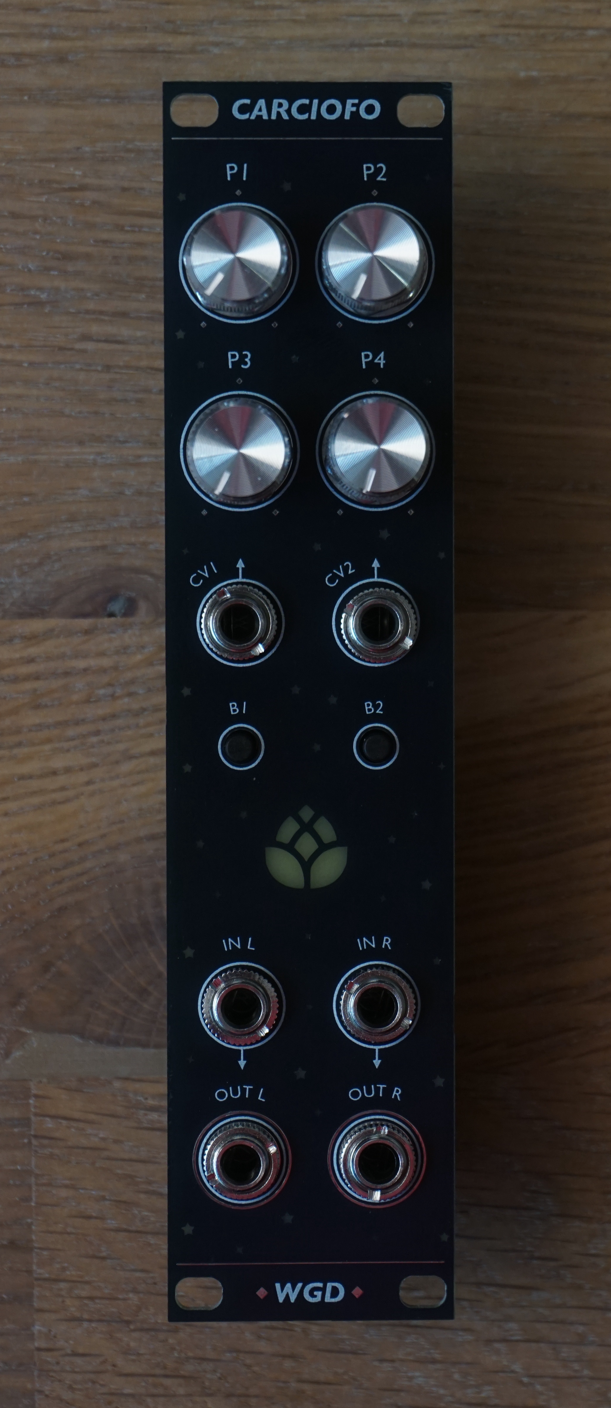
A repository to collect different firmwares for the daisy-based Carciofo module, the 6hp successor of the Löwenzahnhonig. Same four pots and two CV inputs, plus two buttons and an RGB LED.
Flash your module
Flash your module straight from the browser with the Carciofo web flasher. Open it in Google Chrome or Edge, connect the Daisy Seed over USB, hold BOOT and tap RESET to enter the bootloader, then pick a firmware and press flash. It lists every firmware of the latest release together with its controls, and can also flash a local .bin you built yourself.
Prefer to grab the raw binaries? Every firmware is pre-compiled and attached to the latest release.
Manual
The Carciofo manual is a PDF covering the module itself, how to flash it and every firmware of the latest release with all its controls. It is built from this repository, so it always matches the firmwares it comes with.
Controls
One side of the modules front panel has a generic labelling. This table contains a mapping of which control is associated with which pin of the daisy seed.
| Control | Daisy Pin |
|---|---|
| P1 | A0 |
| P2 | A1 |
| P3 | A2 |
| P4 | A3 |
| CV1 | A4 |
| CV2 | A5 |
| B1 | D6 |
| B2 | D7 |
| LED | D5 |
Compilation
This step is only required if you want to modify a firmware or create your own. The firmwares depend on the libDaisy and DaisySP development libraries by Electro-Smith. These are added as submodules to this repository and are most easily fetched when initially cloning the repository as follows:
git clone --recursive https://github.com/wgd-modular/carciofo-firmware
If you cloned without --recursive, fetch them afterwards with git submodule update --init --recursive.
Everything else, the ARM GCC toolchain, make and Python included, is managed by pixi, so nothing has to be installed system-wide apart from pixi itself. It works the same on Linux and macOS (Intel and Apple Silicon); on Windows use WSL. To compile all firmwares run:
pixi run build
The first run sets up the toolchain and compiles both libraries, later runs reuse them. To compile one specific firmware, pass its name:
pixi run build reverb
This places the firmware in src/reverb/build/reverb.bin, ready for the web flasher. pixi run build-libs only rebuilds the libraries, and pixi run clean removes all build output again.
The manual is built in the same way, with its own small environment, into manual/build/carciofo-manual.pdf:
pixi run manual
When working on a single firmware it can be handy to drop into the environment with pixi shell and call make inside the firmware's folder directly.
Writing a firmware
lib/carciofo.h covers the panel so that a firmware does not have to repeat the ADC setup, the button debouncing and the LED timing every time:
#include "../../lib/carciofo.h"

using namespace daisy;
using namespace carciofo;

Carciofo hw;
float gain;

void AudioCallback(AudioHandle::InputBuffer in, AudioHandle::OutputBuffer out,
                   size_t size) {
  for (size_t i = 0; i < size; i++) {
    out[0][i] = in[0][i] * gain;
    out[1][i] = in[1][i] * gain;
  }
}

int main(void) {
  hw.Init();
  hw.StartAudio(AudioCallback);

  while (1) {
    hw.ProcessControls();
    gain = hw.button[BUTTON_1].Pressed() ? 0.f : hw.GetPotWithCv(POT_1, CV_1);
    hw.led.SetHsv(0.33f, 1.f, gain);
    System::Delay(1);
  }
}
ProcessControls() debounces both buttons and pushes the staged LED colour, so it belongs at the top of the main loop. GetPot() and GetCv() hand back 0 to 1, GetPotWithCv() sums the two and clamps. The CV inputs take 0 V to +5 V: 0 V reads as 0 and +5 V as 1. Negative voltages and an unpatched jack read as 0, so a CV summed onto a pot adds nothing until something is patched. The buttons are plain libDaisy Switch objects, the LED takes either RGB or HSV.
Settings that should survive a power cycle go through lib/settings.h. A firmware describes them in a small struct, loads it once at power up and keeps it up to date in the main loop; saving happens on its own two seconds after the last change, and holding both buttons while powering up brings back the defaults:
struct Saved {
  int32_t mode;
  bool operator==(const Saved& o) const { return mode == o.mode; }
};
Settings<Saved> settings;

settings.Init(hw, SLOT_MYFIRMWARE, 1, Saved{0});  // before StartAudio()
mode = settings.Get().mode;

settings.Get().mode = mode;            // in the main loop
settings.Process();
Every firmware has its own slot in the flash, so a new firmware adds one to SettingsSlot in lib/settings.h. Save what the knobs cannot show, like modes and the values on held layers, and let the main layer follow the pots.
Contributing
New firmwares for the Carciofo module are always very welcome. Feel free to open a PR anytime. Each new firmware should be located in a new sub-folder with the same name as the .cpp file together with a README.md file telling users about the controls and other possibly interesting stuff.
That README also becomes the firmware's chapter in the manual, no extra work needed. The first # heading is taken as the firmware's name, any text before the first ## heading as its introduction, and every ## heading becomes a section of the chapter. A section called ## Controls with a table of the controls is shown on the web flasher too and gets highlighted in the manual. Who worked on a firmware and when it last changed is read from the git history of its folder, co-authors included.